








When an existing feeder cannot be withdrawn or its busbar dismantled during a retrofit, current-transformer selection starts with access—not with a catalogue accuracy class. The usable opening, conductor arrangement, shutdown plan, secondary wiring route and protection purpose can eliminate an otherwise suitable CT before its electrical ratings are considered.
Quick Answer: Use a solid-core CT when the primary conductor can pass through the core during assembly and the specified measuring or protection performance is available. Use a split-core CT when retrofit access makes conductor removal impractical. Use a window or donut CT when a cable or busbar can pass through a fixed aperture. Use a core-balance CT around all relevant live conductors when the task is residual or earth-leakage detection. Then verify the ratio, burden, accuracy or protection class, insulation level, frequency, aperture and applicable IEC 61869 requirements.
Which Current Transformer Construction Fits Your Measurement Task?
A current transformer reproduces primary current as a lower, proportional secondary current for meters or protection devices. Construction and application are separate decisions: “solid” and “split” describe whether the core opens; “window” or “donut” describes a common shape; and “core-balance” describes a residual-current application.
A solid core current transformer has a continuous magnetic path and normally requires the conductor to pass through its window before termination. It suits new panels, planned outages and factory assembly. Actual performance depends on ratio, declared burden, accuracy class, frequency and installation—not merely the solid core.
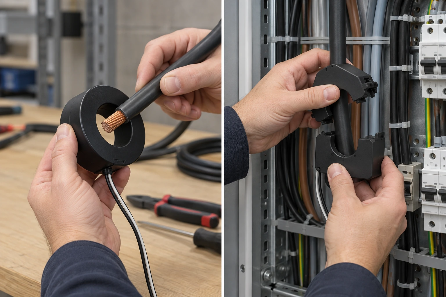
A split core current transformer opens around an existing cable or busbar. It can reduce retrofit rework, but the joint must close correctly and remain undamaged. Accuracy depends on the selected model’s declared class at the intended burden and operating range.
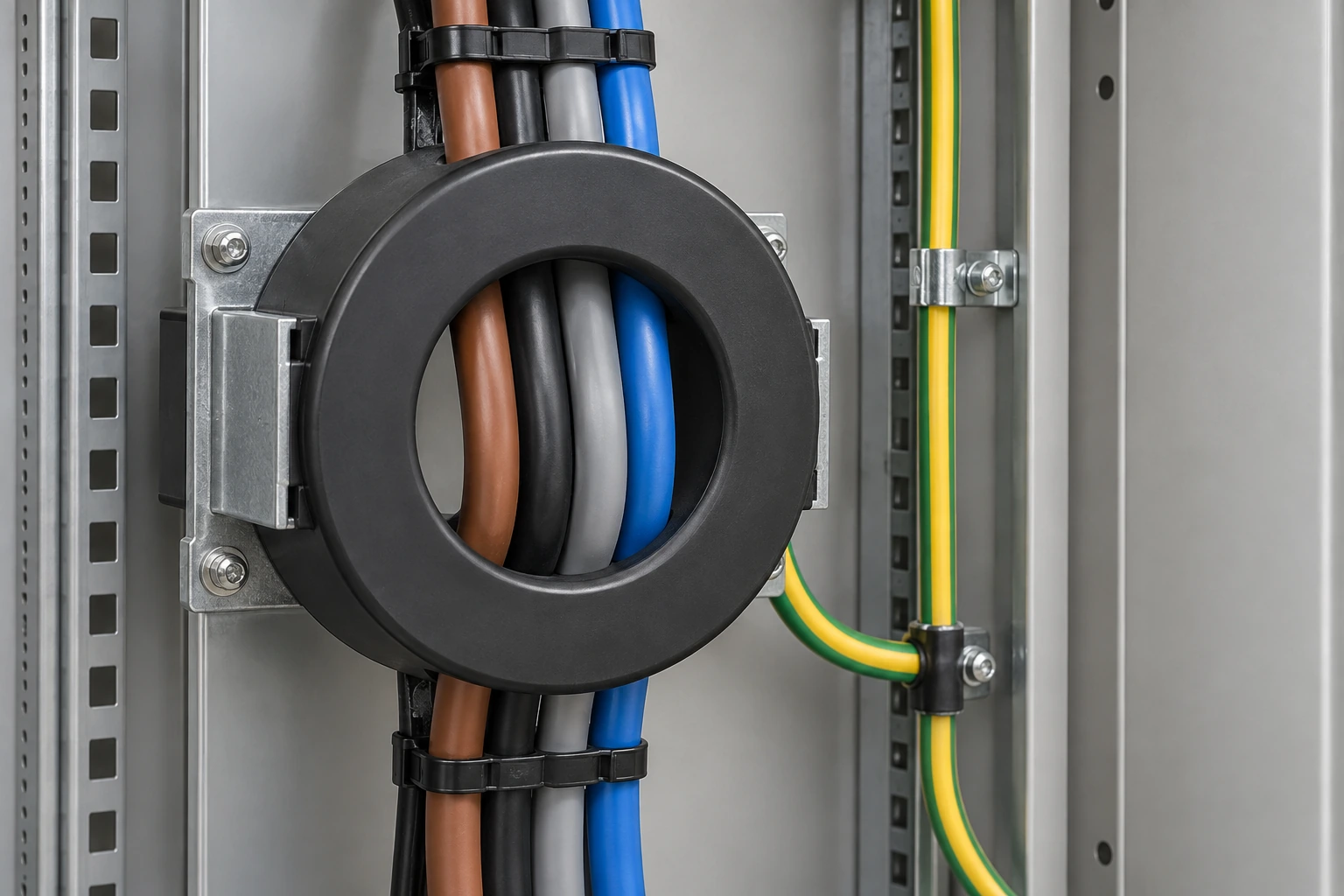
A donut current transformer is a ring-shaped window CT. Aperture size, conductor position and bend radius can be decisive. It can serve metering or protection according to its rated characteristics; shape alone does not establish function.
| CT category | Typical task | Primary-conductor access | Main selection caution |
|---|---|---|---|
| Solid-core | New-build metering or protection | Conductor must pass through the closed aperture | Plan installation sequence and verify declared class at the specified burden |
| Split-core | Retrofit measurement where conductor removal is difficult | Core opens around the conductor | Check joint closure, orientation, clearance and model-specific performance |
| Window/donut | Cable or busbar measurement through a fixed opening | Requires a suitable aperture and routing path | Confirm window dimensions, insulation clearances and conductor geometry |
| Core-balance | Residual-current or earth-leakage protection | All relevant live conductors pass through one core | Do not route only one phase or include the protective conductor |
When Should You Use a Split-Core Instead of a Solid-Core CT?
Choose split-core construction when an existing conductor cannot reasonably be disconnected or threaded through a closed core. Relevant constraints include shutdown limits, terminated cables, inaccessible busbar joints and the risk of disturbing insulation or connections. A split core can simplify installation, but it does not authorize live work; site electrical-safety procedures still govern.
Prefer solid-core construction during assembly, while the conductor route is open, or when an outage makes threading practical. Compare documented performance at the intended burden rather than assuming every solid core is more accurate. Lead length, instrument burden, ratio, frequency and installation all affect the measurement circuit.
How Does a Core-Balance CT Detect Earth-Leakage Current?
If a specification asks “what is core balance current transformer technology intended to detect?”, the direct answer is residual current. All phase conductors—and the neutral where the circuit arrangement requires it—pass through the same aperture. Under balanced conditions, their instantaneous current contributions sum close to zero. Current returning by an unintended path leaves a non-zero residual, which produces a secondary signal for the associated protection device.
The core balance current transformer measures the vector sum of enclosed conductors, not one phase’s load current. The protective conductor stays outside the aperture, subject to manufacturer instructions. Sensitivity and operating time belong to the complete CT-relay-trip scheme, not the ring’s appearance.
What Installation Constraints Matter Inside a Current Transformer Cabinet?
Inside a compact current transformer cabinet, the outline drawing is as important as the ratio. Check the aperture against the cable or busbar, plus external dimensions, terminal access, bending space and split-core opening clearance. Secondary wiring must not obstruct mechanisms, barriers or maintenance access.
Polarity marks should remain visible. Secondary burden includes the instrument and wiring, so conductor size and route length matter. Never leave a CT secondary open while primary current flows; procedures should define shorting, isolation, earthing and test-terminal arrangements.
| Installation condition | Likely direction | Checks before release |
|---|---|---|
| New cabinet with open conductor route | Solid-core or fixed window CT | Assembly sequence, aperture, ratio, burden, class and insulation coordination |
| Existing terminated cable or busbar | Split-core CT | Safe access, core-opening clearance, joint closure and orientation |
| Earth-leakage protection | Core-balance CT with compatible relay | All required live conductors enclosed, protective conductor excluded, scheme tested |
| Long secondary wiring route | Evaluate 1 A against 5 A system practice | Total secondary burden, cable resistance, instrument input and existing standardization |
| Restricted aperture or bend radius | Recheck CT form and conductor routing | No forced cable bends, insulation damage or conflict with required clearances |
Which IEC Requirements Should You Verify Before Ordering a CT?
IEC 61869-2:2012 gives additional requirements for newly manufactured inductive CTs used with measuring instruments or protective devices at rated frequencies from 15 Hz to 100 Hz. IEC 61869-1:2023 provides general requirements for newly manufactured instrument transformers above its stated voltage threshold; its scope directs low-voltage applications to IEC 61869-201. These are product standards, not blanket certifications for an installed scheme.
Identify system voltage, function and destination-market rules, then request declared ratio, burden, accuracy or protection class, frequency, insulation information and test documentation. For protection, coordinate the CT with the relay and fault study. For regulated metering, ask the responsible authority about approval, sealing and verification.
Unsupported compliance language can cause drawing rejection, coordination failure or cabinet rework. Apply routine, type and commissioning tests as specified; passing one test method is not equivalent to unrelated product certification.
How Should Engineers and Buyers Specify a Current Transformer?
- Define the task first. Separate metering, indication, protection and residual-current detection; each has different performance priorities.
- Survey the primary path. Record conductor dimensions, aperture, spacing, clearances, installation sequence and shutdown constraints.
- Calculate the secondary circuit. Include instrument input and lead resistance, then select 1 A or 5 A for the connected equipment and project practice.
- Match documented performance. Specify ratio, class, burden/output, frequency, insulation, polarity and required protection characteristics.
- Plan verification. Define drawing review, inspection, polarity, ratio and wiring checks, appropriate injection, and end-to-end functional testing.
Fuerte manufactures medium-voltage distribution and protection equipment, not current transformers. For projects integrating CT measurement with switchgear or breakers, buyers can review Fuerte’s company and equipment scope and ask for interface information relevant to cabinet layout, breaker control and protection coordination. The CT itself should be sourced and verified against its own manufacturer’s data.
Frequently Asked Questions
What is the difference between a solid-core and a split-core current transformer?
A solid-core CT has a closed magnetic core and normally requires the primary conductor to be threaded through it. A split-core CT opens around an installed conductor, which is useful for retrofits. Neither construction is inherently more accurate in every case; compare the declared class and burden of the actual models under consideration.
What is the difference between a current transformer and a core-balance current transformer?
A conventional CT usually measures current in one primary conductor for metering or protection. A core-balance CT surrounds all relevant live conductors and responds to their residual sum, making it suitable for earth-leakage protection schemes. Its output must be matched to the associated relay or monitoring device.
What are the two main types of current transformers?
By mechanical core construction, the two common groups are solid-core and split-core CTs. By duty, CTs are also commonly distinguished as measuring and protection types. Window, bar, wound and core-balance descriptions address form or application, so a purchase specification should state both construction and duty.
How do you test a core-balance current transformer?
With the equipment safely isolated, inspect conductor routing, polarity, terminals and secondary continuity according to the manufacturer’s procedure. Use an approved primary-injection or simulated residual-current method to verify the CT-relay response, then perform an end-to-end trip test where the protection plan requires it. Never open-circuit an energized CT secondary.
Are split-core CTs accurate enough for energy metering?
They can be when the selected model declares the required metering class at the actual ratio and burden and is installed correctly. Do not decide from construction type alone; verify the datasheet, connected meter, lead burden, conductor position and any utility approval requirements.
Why are 1 A and 5 A CT secondary ratings used?
Both are established secondary-system conventions supported by meters and protective relays. For the same secondary-circuit resistance, the lower current reduces wiring loss and burden because resistive loss varies with current squared, which can help on longer runs. A 5 A choice may align with existing equipment and site practice; compatibility and the full burden calculation should decide.
References
- IEC 61869-2:2012 — Instrument transformers, Part 2: Additional requirements for current transformers
- IEC 61869-1:2023 — Instrument transformers, Part 1: General requirements
- ABB — Current transformers and Rogowski coils
Conclusion
The right CT is the one that satisfies the measurement or protection task and can be installed, wired, tested and maintained within the real cabinet. Start with duty, conductor access and aperture; then verify ratio, burden, class, frequency, insulation and secondary-system compatibility. Treat solid-core, split-core and donut descriptions as construction or form choices, while a core-balance CT serves a residual-current function. Document those distinctions before requesting quotations, and require model-specific evidence rather than relying on generic accuracy assumptions. When CTs must interface with medium-voltage switching and protection equipment, share the single-line diagram, cabinet constraints and relay requirements early. For support coordinating those interfaces with Fuerte equipment, contact Fuerte with the project drawings and operating requirements.