








A current transformer can have the right primary-current rating and still give an unreliable protection or metering signal. The usual specification risk is not a defective unit; it is a mismatch among ratio, accuracy class, connected burden, lead resistance, polarity, and the actual fault or load range.
Quick Answer: Select a CT only after defining its purpose, maximum continuous and fault current, required ratio, 1 A or 5 A secondary, accuracy class, total connected burden, polarity, insulation level, frequency, and saturation requirement. Then verify the complete secondary loop against the applicable IEC 61869 requirements and the relay or meter manufacturer’s input data. Never leave the secondary open while primary current is flowing.
What a CT Does in a Medium-Voltage Protection Chain
If the question is what is a current transformer, the practical answer is that it is an instrument transformer that reproduces primary alternating current as a smaller, specified secondary current for meters, relays, and control equipment. The conductor carrying primary current produces magnetic flux in the core; the secondary winding develops a proportional current that opposes that flux while its circuit is closed. This is the basic answer to current transformer how it works.
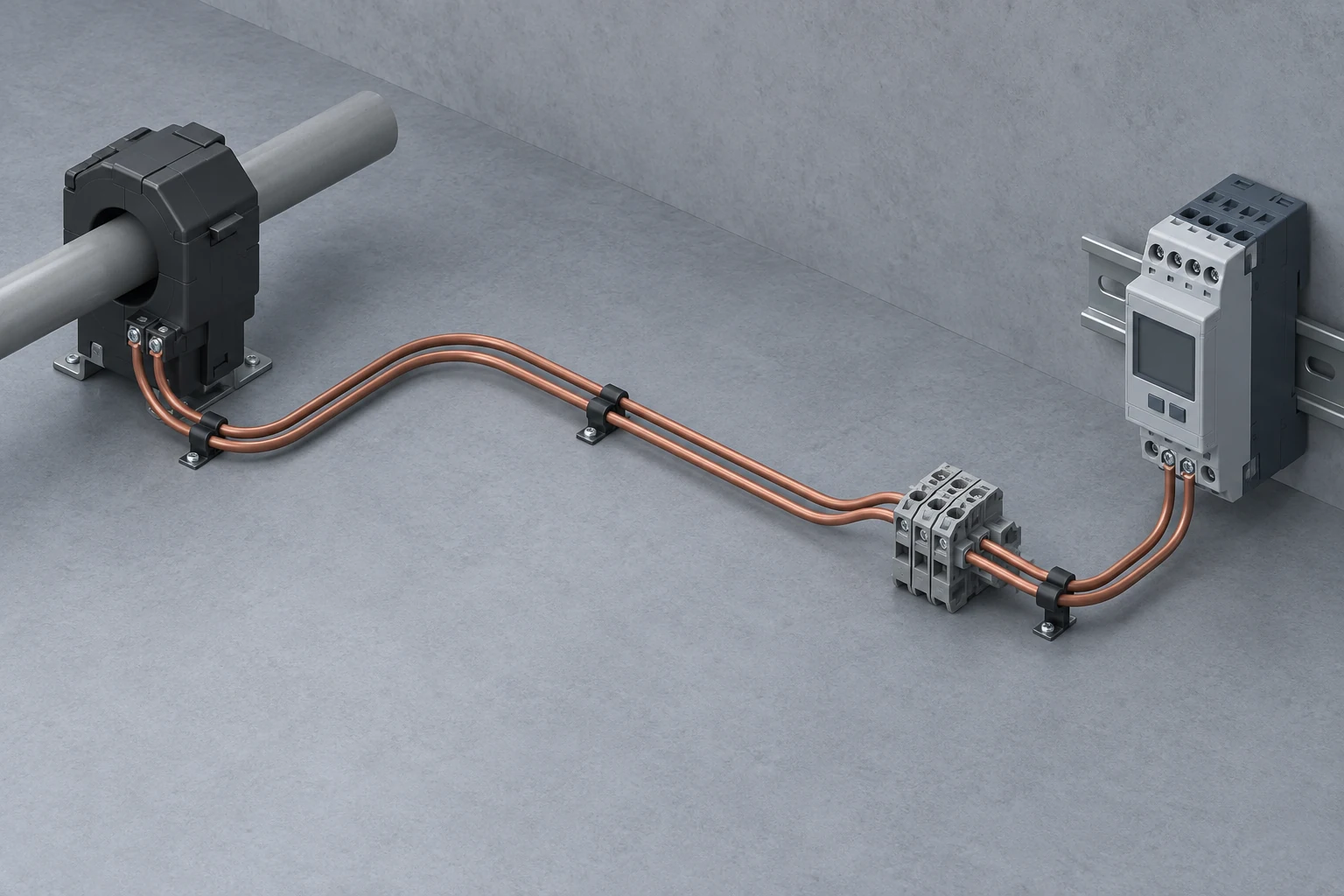
In procurement language, current transformer means more than a ratio stamped on a nameplate. The CT, secondary leads, test blocks, terminals, meter or relay inputs, and earthing arrangement form one measurement chain. In medium-voltage switchgear, current transformers should therefore be coordinated with the protection philosophy and breaker ratings rather than ordered as isolated accessories.
| Selection dimension | Metering CT | Protection CT |
|---|---|---|
| Main objective | Specified accuracy through the intended measurement range | Usable relay signal during abnormal and fault current |
| Core behavior | Saturation behavior may be used to limit downstream exposure, subject to the design | Adequate saturation margin is important for dependable protection |
| Key checks | Ratio, accuracy class, rated burden, normal load range | Ratio, protection class, burden, fault duty, knee-point or transient data when applicable |
| Typical consequence of mismatch | Biased energy or process measurements | Delayed, unwanted, or directionally incorrect relay operation |
How to Match CT Ratio and Secondary Current to the Load
Set the CT Ratio From Normal Load and Fault Current
The primary rating should cover expected continuous loading without sacrificing useful resolution at normal operating current. Protection applications also require the prospective fault current and relay performance at that multiple of rated current. An oversized ratio may make normal-load measurement less useful, while an undersized selection may overload or saturate under the required duty.
A 1 A secondary generally reduces lead burden because conductor loss varies with the square of secondary current. It is often advantageous on long runs between switchgear and a control room. A 5 A secondary remains common where compatible legacy meters, relays, and short wiring runs are present. The decision must match every device in the loop; 1 A and 5 A inputs are not interchangeable without design review.
| Project condition | Design implication | Document to request or verify |
|---|---|---|
| Wide normal-load range | Check low-current accuracy as well as maximum continuous current | Ratio-error and phase-displacement data for the specified class |
| Long secondary cable | Compare 1 A and 5 A options using total loop resistance | Cable length, cross-section, material, temperature basis, and relay input burden |
| High prospective fault current | Assess saturation and protection-class suitability | Excitation or knee-point data and the relevant protection calculation |
| Directional or differential protection | Keep ratio and polarity consistent across all phases and zones | Approved single-line diagram, terminal schedule, and relay matrix |
How CT Polarity Changes Metering and Protection Results
Polarity marks identify the corresponding instantaneous directions of primary and secondary current. P1/P2 normally mark the primary orientation and S1/S2 the secondary terminals. Reversing one CT can reverse its contribution in vector sums, which may distort power calculations or cause directional and differential protection to interpret current incorrectly.
The approved schematic, terminal schedule, and physical labels should agree before energization. A current transformer connection check belongs in commissioning whenever relay current inputs participate in tripping logic; continuity alone does not prove phase identity or polarity.

Which IEC Requirements and Test Records Belong in the Specification?
IEC 61869-1:2023 provides general requirements for newly manufactured instrument transformers within its stated high-voltage scope, including analogue or digital secondary signals used for measurement, protection, and control. IEC 61869-2:2012 adds requirements for newly manufactured inductive CTs used with measuring instruments or protective devices at rated frequencies from 15 Hz to 100 Hz.
These publications are specification and test references, not automatic evidence that a particular product is certified. Procurement documents should identify the applicable edition, national adoption, service conditions, accuracy or protection class, rated burden, insulation requirements, and required type or routine test records. Where editions or regional rules overlap, confirm the governing requirement with the project authority and supplier before approval.
How to Calculate CT Burden Across the Complete Secondary Loop
CT burden is the impedance connected to the secondary, commonly expressed as volt-amperes at rated secondary current. For a simple sinusoidal assessment, apparent burden is derived from the square of secondary current multiplied by total loop impedance. The calculation must include relay or meter inputs, both outgoing and return leads, terminals, test switches, and other series connections.
Longer or smaller conductors add resistance, and the associated burden can move the CT outside its specified accuracy or saturation performance. Use the actual routed round-trip length, conductor properties, and applicable temperature assumption rather than a one-way cable estimate. Confirm that the sum remains within the CT and connected-device requirements, with any project margin stated openly rather than hidden in a generic rule of thumb.
CT Procurement Checklist: Data to Confirm Before Approval
- Define the duty: state whether each core serves metering, protection, or a dedicated function, and identify the normal and fault-current envelope.
- Coordinate the electrical data: select ratio, 1 A or 5 A secondary, frequency, accuracy or protection class, rated burden, insulation level, and saturation data where required.
- Calculate the installed burden: include devices, test blocks, terminals, and the full secondary cable loop.
- Control interfaces: align P1/P2 and S1/S2 orientation, phase identification, terminal numbers, drawings, relay settings, and earthing practice.
- Verify records: review applicable test reports, nameplate data, drawings, and commissioning procedures against the purchase specification.
Fuerte supplies medium-voltage distribution protection equipment; where a project combines CT inputs, protective relays, and switching equipment, its team can help coordinate the requested protection-system documentation. That support does not replace CT manufacturer data or the engineer’s protection study, and it should not be read as a claim that Fuerte manufactures the CT.
When CT Simulation Adds Value to the Protection Study
A current transformer simulation can compare secondary waveform behavior under assumed fault current, burden, remanence, and core data. It is especially useful for differential, restricted-earth-fault, or other schemes sensitive to saturation and transient error. The model is only as reliable as its inputs, so simulation should supplement—not substitute for—verified excitation data, relay requirements, wiring calculations, and commissioning tests.
Frequently Asked Questions
How is a current transformer connected?
The primary path passes through or is connected in series with the monitored conductor, while the secondary is connected as a closed loop to the specified meter or relay input through terminals and test devices. Follow the approved polarity, phase, earthing, and terminal diagram; never improvise changes on an energized CT circuit.
How does a current transformer work?
Alternating primary current creates magnetic flux in the core, inducing a secondary current whose magnitude follows the CT ratio within its specified operating limits. The secondary current then supplies a measuring or protection device, while accuracy depends on burden, frequency, class, and core behavior.
What are S1 and S2 in a current transformer?
S1 and S2 are the polarity-designated secondary terminals corresponding to the primary polarity marks. Their orientation matters for phase-angle relationships, power measurement, directional elements, and differential summation, so it must match the approved drawings.
Why must a current transformer secondary never be left open?
With primary current flowing, an open secondary removes the normal opposing secondary ampere-turns. Core flux and secondary voltage can rise to hazardous levels, creating shock, insulation, heating, and equipment risks. Use an approved shorting arrangement and qualified procedures before disconnecting a secondary device.
How do you perform a burden test on a current transformer?
Under an approved de-energized or controlled injection procedure, measure the secondary circuit voltage and current, or its impedance, across the complete connected loop and calculate VA at the declared secondary current. Include lead and contact resistance, compare the result with the CT and device requirements, and never create an open secondary on an energized primary.
What does a CT ratio of 100/5 mean?
It means that 100 A primary current corresponds nominally to 5 A secondary current under the specified conditions, a ratio of 20:1. It does not by itself state the CT’s accuracy class, burden capability, insulation rating, or saturation performance.
Conclusion
A reliable CT specification describes an installed measurement chain, not just a primary-to-secondary ratio. Begin with the protection or metering duty, then coordinate normal current, fault current, secondary rating, class, burden, cable route, polarity, saturation data, and the applicable standard. Verify that drawings, terminal schedules, relay inputs, and test records all describe the same arrangement. This disciplined approach reduces avoidable commissioning disputes and makes later troubleshooting far more direct. Above all, treat the secondary loop as a safety-critical circuit: keep it closed or correctly shorted whenever primary current may flow, and require qualified personnel to follow the project’s approved procedure.
References
- International Electrotechnical Commission, IEC 61869-1:2023, Instrument transformers—Part 1: General requirements.
- International Electrotechnical Commission, IEC 61869-2:2012, Instrument transformers—Part 2: Additional requirements for current transformers.
- ABB, Current Transformers and Rogowski Coils, product and application overview.
For coordinated medium-voltage protection-equipment documentation and project-specific interface questions, contact Fuerte with your single-line diagram, CT schedule, relay data, and applicable standard.