








When a vacuum circuit breaker fails to close during commissioning, the breaker itself is often blamed first. The cause may instead be a permissive contact, a low control voltage, a charged-spring indication, a trip coil still energized or a mechanical interlock holding the truck out of position. Because a VCB is an electromechanical chain, troubleshooting one component in isolation can waste an outage window. This guide maps the control and mechanism functions and turns them into practical checks.
Summary: A VCB closes only when its mechanical mechanism is ready and every electrical and mechanical permissive is satisfied. The close coil releases stored energy; a trip coil or opening latch releases the contacts when protection operates. Anti-pumping logic prevents repeated close commands after a trip. IEC 62271 requirements and the approved switchgear schematic define the exact circuit. Verify control voltage, coil resistance, auxiliary contacts, interlocks, spring charging, travel and timing before changing a breaker.
What are the functions of VCB closing and trip coils?
The closing coil receives a controlled pulse and releases a latch so the stored-energy mechanism drives the moving contacts closed. The trip coil operates an opening latch, allowing the mechanism to open the contacts quickly when a protection relay, local pushbutton or emergency circuit sends a trip command. Some breakers have separate first-trip and second-trip coils for redundancy.
Coils are designed for a specified control voltage, pulse duration and resistance. A low supply, loose terminal or incorrect coil can prevent operation even when the interrupter and mechanism are healthy. Measure voltage at the coil terminals during operation rather than only at the battery or control-panel supply. Record the coil identifier and wiring revision in the test sheet.
What is a mechanical interlock for circuit breakers?
A mechanical interlock blocks a physically unsafe action. Examples include preventing a breaker from closing while it is between service and test position, blocking racking while the breaker is closed, or preventing an earth switch from closing while the main path is energized. The linkage, shutters, keys and position flags must correspond to actual contact positions.
Electrical interlocks provide the same permissive logic through auxiliary contacts and control wiring. Neither type should be bypassed casually. During commissioning, test each intended and prohibited sequence, including loss and restoration of control power. The VCB mounting and retrofit guide helps identify interfaces that commonly affect interlock alignment.
How does anti-pumping work in a vacuum circuit breaker?
Anti-pumping prevents a breaker from repeatedly closing if a close command remains present while a trip command opens it. The control circuit allows one close operation, blocks a second close until the close command is removed and then requires a new intentional command. This protects the mechanism and limits repeated energization of a faulted feeder.
Test anti-pumping with the approved sequence: hold the close command, initiate a trip, confirm one opening and verify that the breaker does not reclose until the close signal is reset. Check the relay logic and auxiliary-contact timing. The function is often implemented in the control circuit, so a wiring revision can change behavior without any mechanical modification.
What should be checked when a VCB fails to close?
Start with safe, non-invasive checks: service or test position, spring-charged indication, control-fuse status, local/remote selector, trip circuit healthy indication and interlock position. Then measure control voltage at the close coil while the command is applied. If voltage is present but the coil does not move, inspect coil resistance, latch movement and mechanical binding.
If the breaker closes and immediately trips, investigate protection pickup, anti-pumping, undervoltage release, shunt-trip wiring and an actual feeder fault. Do not defeat a trip circuit to obtain a close indication. A vacuum circuit breaker configuration should be checked against its original schematic and approved protection settings.
How do control circuits and mechanisms work together?
| Function | Electrical element | Mechanical result | Commissioning evidence |
|---|---|---|---|
| Close command | Close coil and permissive contacts | Latch releases; contacts close | Coil voltage, timing and position indication |
| Trip command | Trip coil, relay or emergency circuit | Opening latch releases; contacts open | Trip time, pole simultaneity and trip-free test |
| Anti-pumping | Control relay or logic contact | Blocks repeated close after a trip | Held-close test and reset confirmation |
| Position permissive | Auxiliary and truck-position contacts | Blocks unsafe close or racking | Service/test interlock matrix |
| Energy readiness | Spring-charge motor and limit switch | Stores energy for a reliable stroke | Charge time, indication and limit-switch check |
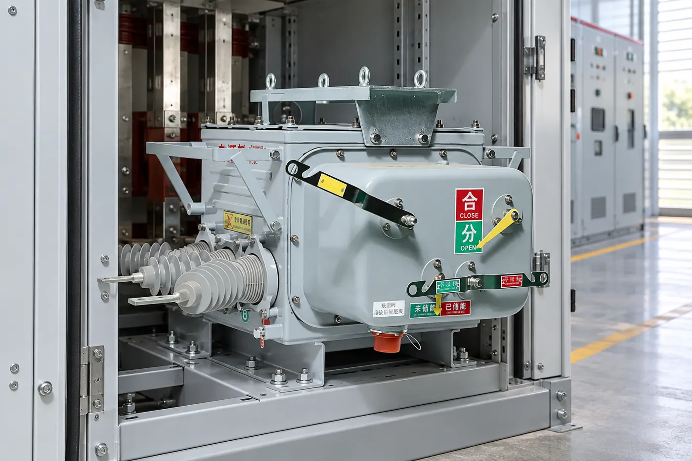
Which control and mechanism checks belong in commissioning?
| Check group | Typical observations | Action when outside expectation |
|---|---|---|
| Supply and coils | Voltage, polarity, pickup, resistance, terminal tightness | Trace supply and wiring before replacing parts |
| Auxiliary contacts | 52a/52b state, continuity and timing | Correct adjustment or replace damaged contact block |
| Mechanism | Spring charge, travel, bounce, lubrication and latch release | Use manufacturer service procedure |
| Interlocks | Service/test/earth-switch permissive matrix | Stop and correct unsafe sequence; do not bypass |
| Protection interface | Trip command, lockout, anti-pumping and remote control | Compare with approved relay and control drawings |
What standards and records support a safe VCB control scheme?
IEC 62271 series standards address switchgear ratings, mechanical operation, control circuits and tests. IEEE C37 standards may apply where the purchaser uses North American practice. Consult the IEC Webstore or IEEE Standards for the current product scope. The standard does not replace the project-specific interlock matrix or protection study.
Retain the final schematic, terminal schedule, coil data, interlock test sheet, timing record and as-left settings. A certificate for the breaker does not prove that an altered panel wiring scheme is safe. Any modification should be reviewed, tested and documented before energization.
How should teams maintain VCB controls and mechanisms?
- Keep the control schematic and wiring revision beside the asset record.
- Trend coil voltage, resistance, operation time, spring-charge time and contact timing.
- Inspect mechanical linkages, latches, lubrication, shutters, keys and position flags.
- Test anti-pumping, trip-free, local/remote, service/test and earth-switch interlocks after changes.
- Investigate any slow, uneven or repeated operation before returning the feeder to service.
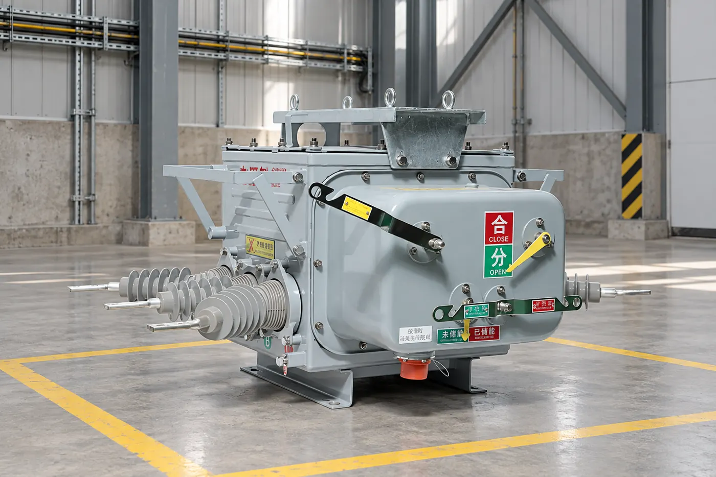
Fuerte can align a medium-voltage VCB configuration with the buyer’s control voltage, mounting and interlock requirements. Provide the panel schematic and duty details through the contact page for a documented review.
Frequently asked questions
What is a mechanical interlock for circuit breakers?
It physically blocks an unsafe action, such as closing a breaker outside its service position or racking while closed. Its operation must be tested with the actual breaker and earth-switch arrangement.
What are the functions of VCB closing and trip coils?
The close coil releases the mechanism to close contacts; the trip coil releases the opening latch. Both require the specified control voltage, wiring and pulse conditions.
What should be checked when a VCB fails to close?
Check position, spring charge, control fuses, permissive contacts, trip-circuit status and voltage at the close coil. If the coil is energized but the mechanism does not move, investigate coil and latch condition.
What is anti-pumping in a vacuum circuit breaker?
It blocks repeated closing when a close command remains active after a trip. A fresh close command is required after the original command resets.
What is the purpose of a circuit-breaker interlock?
It prevents a mechanical or electrical sequence that could damage equipment or expose personnel, such as closing into an earth switch or racking a closed breaker.
What is the typical resistance of a VCB tripping coil?
Resistance is model- and voltage-specific; there is no universal value. Measure it against the manufacturer’s data at a controlled temperature and investigate phase or unit deviations.
References
- IEC Webstore, IEC 62271 standards.
- IEEE Standards, IEEE C37 switchgear requirements.
- International Electrotechnical Commission, switchgear conformity resources.
- CIGRE, operation and maintenance guidance.
A reliable VCB is a coordinated chain: permissives allow the command, the coil releases the latch, the mechanism moves at the right speed and the indication proves the result. Commission and maintain the chain as one system. Contact Fuerte for a configuration review tied to the approved drawings.
What should be included in the interlock matrix?
List every operating state in rows and every command in columns: close, trip, rack in, rack out, earth switch, local control and remote control. Mark whether each action is permitted, blocked or permitted only with a key exchange. Include loss of auxiliary power and a stuck close signal so the anti-pumping response is explicit.
Use the matrix during factory acceptance and site acceptance testing. Each result should identify the terminal or mechanism that created the permissive, the expected indication and the actual observation. This simple record makes later troubleshooting faster because it distinguishes a control-logic change from a mechanical adjustment.
Control circuits should also be checked for polarity, fuse discrimination and supply sag during simultaneous operations. Battery-backed systems can show an acceptable open-circuit voltage yet drop below the coil pickup value under load. Measure at the breaker terminals and confirm the minimum operating voltage in the project specification.
Where remote SCADA commands are enabled, verify command ownership and feedback so a local technician cannot be surprised by an unplanned close. The final record should state who can issue each command, what feedback proves completion and which lockout or permit blocks it during maintenance.
After any control modification, repeat the full matrix rather than testing only the changed terminal. A new permissive can alter a previously safe sequence, and a failed auxiliary contact can make the indication disagree with the primary contacts. Functional testing should end with the breaker in the documented safe state.
Keep the test evidence with the panel identification and software or relay revision. That trace lets operations staff distinguish a real feeder trip from a control-circuit test and prevents an old schematic from being used during a future outage.