








A replacement breaker can fit inside an existing panel and still be unsuitable for service. The primary contacts may engage differently, a cell switch may be driven beyond its intended movement, or the trip circuit may not perform the same function. These are integration problems, not issues solved by choosing a higher voltage or interrupting rating. A retrofit should start with the installed equipment and its operating scheme, then define what the new assembly must preserve or deliberately change. This guide covers the field survey, mounting choice, control mapping and acceptance records needed to turn a proposed VCB replacement into a controlled project.
What should the buyer confirm first?
Plan a VCB retrofit as a match between a defined replacement and a defined receiving assembly. Survey the existing cell, primary connections, truck or mounting, earthing, shutters, interlocks, secondary plug and control functions. Select an engineered direct replacement, an approved adaptation or a wider switchgear replacement according to that evidence. Verify the breaker and the affected assembly separately. ABB describes panel-matched bushings and trucks with cell-based production testing; Siemens highlights mechanism-operated cell switch actuation in its replacement products. These examples show why fit and functional compatibility need evidence, not an assumption based on external dimensions.
What must the field survey record?
Identify the installed switchgear, cell and breaker, including serial numbers and drawing revisions. Record primary-contact arrangement, mounting datums, insertion path, secondary connector, racking or locking features, earthing path and access constraints. Use controlled measurements and drawings; photographs alone cannot establish tolerances or the condition of concealed features.
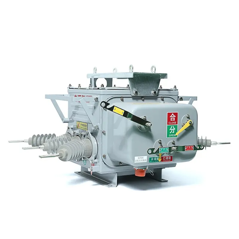
The survey also needs the network duty and the condition of the equipment that will remain. Replacing the breaker does not remedy every busbar, insulation or enclosure problem. The VCB selection guide helps connect the replacement to the current network study.
Which retrofit route fits the existing equipment?
| Route | What needs definition | Main review point |
|---|---|---|
| Engineered direct replacement | Named receiving cell and replacement configuration | Evidence of primary, secondary and interlock compatibility |
| Adapted mounting or truck | Controlled adapter design and changed interfaces | Responsibility for altered mechanical and insulation boundaries |
| Fixed replacement | Connection, isolation and maintenance arrangement | Access and service functions differ from drawout equipment |
| Wider assembly replacement | Condition and duty of retained equipment | Project scope may extend beyond the breaker |
Choose the route after the survey, not from the lowest equipment price. A direct-replacement claim should identify which receiving configurations it covers. ABB’s retrofit description explicitly links its solution to panel-matched bushings, trucks, interlocking and testing in a switchgear cell.
How should the old and new control circuits be compared?
Map functions first and terminal numbers second. Compare trip and close supplies, command paths, auxiliary indication, spring-charged or ready signals where applicable, local/remote selection and relevant permissives. Preserve the intended protection and interlocking behavior or document the approved change.
A matching secondary plug shell does not prove the same pin assignment. Likewise, a mechanism-operated cell switch can depend on movement and force as well as position. Siemens’ replacement-breaker page specifically discusses controlling MOC system velocity in its own solution. Use the VCB component identification checklist when the original interface parts are uncertain.
Which evidence changes when the breaker changes?
IEC 62271-100 covers circuit-breakers within its scope. IEC 62271-200:2021 addresses metal-enclosed assemblies above 1 kV and up to and including 52 kV, with its stated conditions. A breaker report alone does not establish the characteristics of a modified assembly, including affected interlocks or internal-arc arrangements.

Assign responsibility for assessing the modification and defining what evidence remains applicable. Do not automatically promise that an old assembly classification transfers unchanged, or require every test to be repeated without considering the actual change. The affected design and project requirements determine the review.
What should be agreed before the outage starts?
Freeze the drawings, replacement scope, tools, qualified personnel, test plan, hold points and return-to-service criteria. Establish what will happen if fit or function does not match the approved design. Keep the original configuration record available so an unplanned field alteration does not become the only way to finish the outage.
Commissioning should verify the functions affected by the work, including the complete trip chain and defined racking or interlock states where relevant. The VCB commissioning tests guide explains why these site checks complement rather than replace design evidence.
FAQ
Does matching busbar spacing prove a retrofit fits?
No. Primary engagement, mounting, secondary circuits, earthing, racking and interlocks must also be verified for the receiving equipment.
Can the same secondary plug be wired differently?
Yes. Compare the controlled pin assignments and functions instead of relying on connector appearance.
Does a new breaker increase the existing switchgear’s fault rating?
Not automatically. The retained assembly’s capabilities and the complete modification must be assessed separately.
What should happen if fit is wrong during the outage?
Follow the agreed hold and escalation process. Do not force the unit into place or bypass interlocks to complete the job.
Summary
A successful retrofit preserves the intended electrical and operating functions of a known receiving assembly. Start with the field survey and current duty study, choose a route supported by interface evidence, and map the control functions before committing to the outage. Keep breaker qualification distinct from the assessment of the modified switchgear. Never use apparent fit or an unchanged connector shell as a substitute for functional verification. The public OEM examples and standard scopes were checked on 15 October 2026; no specific cell has been surveyed here. FUERTE’s vacuum circuit breaker retrofit enquiries should include receiving-equipment identity, drawings and the proposed integration scope.