








When a protection relay trips a medium-voltage feeder, the breaker may open in a few cycles, yet the visible handle movement tells only part of the story. The contacts must separate at the correct speed, the vacuum interrupter must recover dielectric strength and the mechanism must complete its travel without bounce or rebound. If any link is weak, the vacuum circuit breaker arc can restrike or fail to clear. This article explains the interruption sequence and the measurements engineers use to verify it.
Summary: In the operating principle of vacuum circuit breaker operation, a mechanism separates contacts inside a sealed vacuum interrupter; a metal-vapor arc forms, is constrained by the contact geometry and extinguishes near the next current zero. The gap then recovers insulation rapidly. Reliable interruption depends on contact material, travel, speed, pressure, timing, insulation coordination and the protection system. Verify the complete breaker to IEC 62271 or the buyer’s IEEE C37 specification; a vacuum environment does not eliminate every arc phenomenon.
What happens to the vacuum arc at current zero?
As contacts part, current continues through an arc made from vaporized contact material. The contact shape produces a magnetic field that spreads or rotates the arc, limiting local heating and erosion. In alternating current, the current naturally reaches zero each half-cycle. At that instant the vapor supply falls, the plasma collapses and the open gap begins to regain dielectric strength.
Recovery must be faster than the transient recovery voltage across the contacts. If the voltage rises before the gap has recovered, a restrike can occur. That is why contact material, gap distance, opening speed, circuit parameters and external insulation coordination all matter. The vacuum circuit breaker product range should be reviewed with the network fault and switching study rather than as a standalone component.
Can arcing happen in a vacuum?
Yes. A vacuum contains too few gas molecules for a conventional gas arc, but the contacts release metal vapor when they separate. That vapor supports a short-lived vacuum arc until current zero. The design objective is controlled, repeatable extinction and rapid dielectric recovery, not the absence of an arc.
Contact erosion changes the gap and the surface condition over the breaker life. Excessive erosion can reduce interruption margin or affect contact pressure. Inspect the manufacturer’s wear indicator and record operations, contact resistance and timing so trends are visible before the device reaches its limit.
How does the operating mechanism influence interruption reliability?
The vacuum circuit breaker mechanical operating mechanism stores energy and releases it to drive the moving contact. Springs, links, dampers, latches and the trip or close coil determine opening and closing speed. A sluggish mechanism can lengthen arcing time; bounce can produce repeated contact events; insufficient travel can reduce dielectric margin.
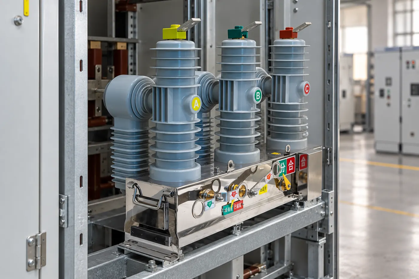
Measure opening and closing time, pole simultaneity, travel, overtravel and contact wipe with instruments suited to the breaker. Check lubrication, fasteners, spring charging, auxiliary contacts and trip-free behavior. A mechanism can pass a visual inspection and still fail a timing test, so commissioning should establish a baseline for future comparisons.
How do contact wear and erosion affect interruption?
Each interruption removes a small amount of contact material. The rate depends on fault current, switching duty, contact design and the number of operations. Wear can increase contact gap or reduce contact pressure; it can also change the magnetic field that controls the arc. The correct acceptance limit is the manufacturer’s measured or indicated wear value, not a universal millimeter figure.
Contact resistance is a useful companion measurement. A rising or unbalanced result may indicate contamination, looseness, poor contact pressure or a damaged conductor path. Compare the phase values at the same test current and temperature, then investigate a trend rather than reacting to one unexplained reading.
How do a vacuum breaker and its interruption sequence compare with other media?
| Feature | Vacuum interruption | What the system must still provide |
|---|---|---|
| Arc medium | Metal vapor from contacts in a sealed bottle | Suitable contact material and arc-control geometry |
| Extinction point | Natural current zero in AC | Recovery faster than transient recovery voltage |
| Insulation recovery | Rapid across the open bottle gap | Correct gap, travel, dielectric coordination and integrity |
| Mechanical dependence | High; speed, travel and pressure affect duty | Healthy mechanism, coils, latches and timing |
| Maintenance evidence | Integrity, resistance, timing and wear | Documented baseline and trend records |
Which factors decide arc-interruption performance?
| Factor | Engineering question | Verification |
|---|---|---|
| Fault current | What current and X/R ratio can the breaker face? | Short-circuit study and rated interrupting data |
| Transient recovery voltage | How quickly does voltage rise after current zero? | System study and applicable type-test envelope |
| Contact travel and speed | Does the mechanism reach the designed gap on time? | Motion and timing test |
| Vacuum integrity | Has the sealed interrupter retained dielectric strength? | Manufacturer-approved integrity test |
| Control and protection | Will the trip command reach every pole reliably? | Relay, coil, auxiliary and trip-free checks |
How do you test contact resistance and arc-interruption readiness?
Use a calibrated low-resistance ohmmeter at the manufacturer’s specified test current and compare all poles. Then perform timing and travel tests for opening, closing, bounce and pole simultaneity. A vacuum integrity test checks the bottle; insulation tests check the assembled breaker to earth and across open contacts. Do not substitute one test for another.

Testing should follow the equipment manual, site safety rules and the applicable IEC 62271 or IEEE C37 requirements. The vacuum circuit breaker test guide can support a documented sequence. Keep instrument calibration, ambient conditions, test voltage and acceptance criteria in the record.
Which standards govern the vacuum circuit breaker principle?
IEC 62271 series standards define ratings, dielectric tests, temperature rise, mechanical endurance and interruption duties for high-voltage switchgear. IEEE C37 standards may apply where the buyer’s specification uses North American classifications. The IEC Webstore and IEEE Standards sites provide the current scope; always identify the exact edition in the tender.
Passing a type test does not remove the need for routine tests, installation checks and coordination with protection. Unsupported claims about “arc-free” operation or universal fault performance are misleading and can create commissioning risk.
How should a buyer specify a vacuum circuit breaker?
- State system voltage, insulation level, continuous current, short-circuit current and application duty.
- Define the required operating mechanism, control voltage, trip and close circuits, interlocks and indication.
- Specify contact travel, timing, contact resistance, vacuum-integrity and dielectric test records.
- Confirm mounting, busbar interfaces, CT or sensor arrangement and maintenance clearances.
- Set a baseline at commissioning and trend wear, resistance and timing against the same criteria.
Fuerte supports medium-voltage breaker specifications for utility and EPC projects. For operating and maintenance detail, see the 12 kV VCB operation guide, then use the contact page to submit the required duty and standards.
Frequently asked questions
What is the working principle of a vacuum circuit breaker?
Contacts separate inside a sealed vacuum interrupter, a metal-vapor arc forms, and the arc extinguishes at the next AC current zero. The contact gap then recovers dielectric strength.
How is an arc extinguished in a vacuum circuit breaker?
Contact geometry controls the metal-vapor arc until current zero, after which the vapor condenses and the gap regains insulation. Recovery must exceed the transient recovery voltage.
Can arcing happen in a vacuum?
Yes. Contact vapor can support a short arc even though there is no conventional gas discharge. Correct contact material and interruption timing control it.
What is arc interruption in a circuit breaker?
It is the controlled extinction of current after contacts open, followed by dielectric recovery that prevents restrike. Fault level, mechanism speed and recovery voltage all matter.
How do you test the contact resistance of a vacuum circuit breaker?
Inject a calibrated DC test current through the closed main path, measure the millivolt drop and compare phase values with the manufacturer’s limits and previous records.
What are the common failure modes of vacuum circuit breakers?
Common problems include loss of vacuum integrity, contact wear, high resistance, slow or uneven mechanism travel, coil or auxiliary-circuit faults and incorrect protection wiring. Test trends help identify the cause.
References
- IEC Webstore, IEC 62271 switchgear standards.
- IEEE Standards, IEEE C37 breaker requirements.
- International Electrotechnical Commission, high-voltage testing resources.
- CIGRE, circuit-breaker interruption guidance.
A vacuum breaker interrupts an arc through a coordinated sequence of contacts, current zero, dielectric recovery and mechanism motion. Specify and test that sequence as a complete system; the word “vacuum” alone is not a performance guarantee. Contact Fuerte for a duty-based breaker review.
How does system coordination protect the interruption margin?
The breaker is evaluated against the network that feeds it. Source impedance, transformer size, cable length, fault X/R ratio and the relay clearing time shape the current and recovery voltage seen at the contacts. A breaker selected from a nominal voltage and current line alone may therefore be exposed to a more severe transient than the quotation assumed.
Design teams should exchange the short-circuit study, protection curves, cable data and switching scenarios before freezing the specification. Include motor or transformer inrush and any capacitor switching that can produce a steep transient. The final type-test envelope, routine-test record and commissioning results should all point back to the same approved system assumptions.
During acceptance, witness the trip path from relay output to coil and contact movement, then verify the breaker opens on each protected pole. Retain the waveform or timing printout where the test instrument supports it; a dated trace makes later investigations much more reliable than a handwritten pass statement.
For retrofit work, compare the replacement breaker’s contact travel and terminal geometry with the original cubicle before the outage. A change in mechanism stroke or auxiliary-contact timing can affect interlocks and relay logic even when the voltage and current nameplate values appear identical.