








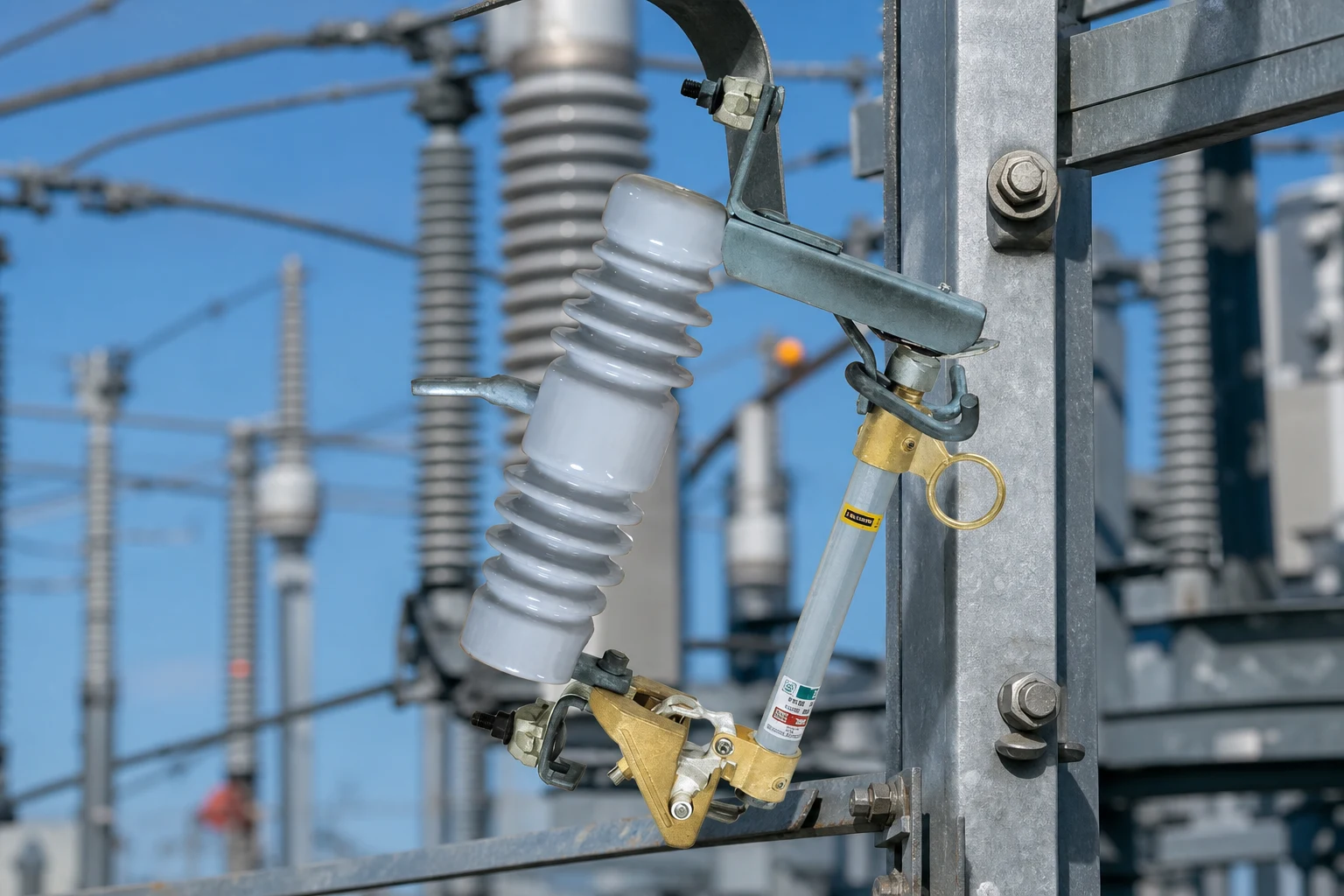
Review a transformer fuse cutout application by confirming transformer data, fault level at the mounting point, physical mounting context, and coordination boundaries before you lock a cutout class or fuse link plan. A primary-side cutout on an overhead distribution transformer clears overcurrent and drops open for visible isolation, but the correct specification still depends on engineering inputs—not on transformer kVA alone. For a related technical topic, see What installation context should a pole-mounted fuse cutout review include?.
This guide is for utility, EPC, and industrial buyers who already know a cutout belongs in the protection scheme and now need a disciplined review before RFQ release. For cutout operating principle, see how a fuse cutout works. For the wider fuse cutout product line, use the category page as the commercial entry point.
Summary: A transformer fuse cutout review is complete only when transformer nameplate data, the fault current at the mounting point, physical arrangement, and approved fuse-link coordination are reconciled. IEEE C37.41 and C37.42 provide the distribution-cutout framework; they do not turn transformer kVA alone into a model selection. Attach the single-line diagram, fault-study reference, mounting sketch, and link plan to the RFQ.
Why should a transformer fuse cutout be reviewed before it is specified?
Distribution projects often arrive at the cutout stage with a transformer nameplate and a line voltage, but without a reconciled fault study at the pole. That gap creates two predictable errors: a transformer fuse cutout that is electrically adequate on voltage yet marginal on interrupting duty, or a protection package that clears faults but trips on normal transformer energization because coordination was treated as a fuse-link afterthought.
A structured application review separates three decisions that buyers sometimes collapse into one purchase line item:
| Decision layer | Question the review must answer | Typical owner |
|---|---|---|
| Application fit | Is a dropout expulsion cutout the intended primary-side device for this transformer arrangement? | Protection engineer / utility standards |
| Cutout class | Do rated voltage, continuous current, and interrupting capability match the confirmed fault and load data? | Specifier with fault study inputs |
| Fuse link and coordination | Which link size and speed class fit the approved coordination study? | Protection engineer; detailed link work in sibling article |
Important: Treat the review as a documentation checkpoint, not a catalogue shortcut. Source context: IEEE C37.41 application scope for distribution cutouts and fuse mountings.
Which transformer and fault inputs define the primary-side review?
Start with the transformer identity and the electrical point where the cutout will sit. Nameplate kVA, primary voltage, vector group, and impedance (%Z) help the protection engineer relate secondary faults to primary current, but they do not replace a fault calculation at the cutout terminals.
Collect the following inputs together rather than in email fragments:
| Input | Why it matters in review | Common gap |
|---|---|---|
| Transformer kVA and connection | Sets continuous load context and energization behavior | kVA copied without vector group or tap position |
| Primary voltage and grounded/neutral arrangement | Defines rated cutout voltage class | Using nominal voltage only, ignoring swells |
| Available fault current at cutout location | Drives interrupting rating review | Using substation fault only, not pole location |
| Downstream conductor and load scope | Confirms continuous current class | Mixing branch and transformer protection scopes |
Use the cutout-class vocabulary from the owner’s engineering standard, then return to transformer-specific fault data for this application.
Secondary-side faults reflect onto the primary as current the cutout must recognize. The review should therefore cite the approved fault study or utility data sheet for the exact pole, not a generic table from a unrelated feeder.
How do mounting location and conductor orientation change the review?
Physical context changes what “fits” even when two poles share the same kVA and voltage. A cutout mounted on the transformer pole sees different conductor approach, working clearance, and hardware loading than a cutout on an adjacent line pole feeding the transformer.
Document these field items before final specification:
- Pole or structure class and intended mounting bracket option
- Conductor direction, phase orientation, and jumper length to the transformer bushings
- Working space for fuse link replacement and visible dropout verification
- Surrounding hardware such as arresters, switches, or secondary racks that affect approach angles

Mechanical compatibility is part of the application review. If the cutout mounting geometry conflicts with the approved conductor layout, crews may install unintended stress on the fuse tube or insulator, even when electrical ratings look correct on paper.
Where do fuse-link coordination inputs belong in the application review?
Coordination belongs in the review file even when the cutout purchase order is separate from the fuse link order. Upstream reclosers, downstream feeder fuses, and transformer damage curves all constrain what the primary cutout plus fuse link combination may do during a fault or inrush event.
At this stage, record the coordination boundary rather than redrawing curves in the article:
| Coordination topic | What to capture in the review | Where detailed selection lives |
|---|---|---|
| Upstream recloser or breaker curve | Device ID, setting basis, single-line reference | Owner protection study |
| Transformer inrush and damage boundaries | Study reference and assumed energization duty | Owner / transformer OEM data |
| Fuse link speed class and size | Approved link family and size list | Approved expulsion fuse-link schedule |
This article intentionally does not expand K-speed, T-speed, or time-current curve methodology. That work belongs in the expulsion fuse link article so transformer application review stays focused on inputs and document completeness.
Tip: When two bidders propose different link speeds for the same kVA, ask each to map its proposal to the same approved coordination study rather than comparing list prices alone. Source context: IEEE C37.42 cutout and fuse-link scope.
Which documents should be checked before the cutout is specified?
Utilities and EPC teams reject late surprises when drawings, studies, and nameplate data disagree. Before cutout specification is frozen, align at least these document types:
| Document | Review question |
|---|---|
| Single-line diagram | Is the cutout shown on the correct side of the transformer primary? |
| Fault study or utility data sheet | Does available fault current at the pole support the proposed interrupting class? |
| Transformer nameplate and approved datasheet | Do voltage, kVA, and connection match the drawing? |
| Owner protection standard or material spec | Are cutout type, insulator material, and hardware options allowed? |
| Installation detail | Do conductor orientation and bracket options match field hardware? |
If any item is missing, mark the specification as conditional and request the revision before PO release. A cutout model number without diagram context is not a complete application review.
What belongs in an RFQ for transformer overhead protection?
An RFQ should make the application review auditable for suppliers. Include:
RFQ input list
- Transformer kVA, primary voltage, vector group, impedance basis if applicable, and tap position reference
- Confirmed available fault current at the cutout mounting point
- Continuous load current and planned spare fuse link strategy
- Cutout rated voltage and interrupting requirements tied to the study
- Mounting bracket preference, conductor size, and orientation sketch or photo
- Insulator material preference if the owner standard requires porcelain or polymer
- Applicable standard family requested in the contract (for example IEEE C37.42 or IEC 60282-2 scope as cited by owner)
- Required drawings, type-test excerpts if mandated by owner, and delivery/incoterms context
Ask bidders to confirm exceptions explicitly. Two proposals with the same model number can still differ in bracket hardware, link compatibility, or included accessories.
When is an FSC-1-1 enquiry a practical next step?
Once the application review is complete, a published product page can anchor a commercial conversation without replacing engineering approval. The FSC-1-1 drop-out fuse cutout page lists, for that model only:
| Parameter (FSC-1-1 page) | Published value |
|---|---|
| Voltage class | 10–15 kV |
| Continuous current options | 100 A / 200 A / 300 A |
| Breaking current | 8 kA |
| Creepage distance | 220 mm |
| Standard cited on page | IEC 60282-2 |

Fit Boundary
Those values apply to FSC-1-1 only. They do not prove suitability for your pole until fault current, coordination, mounting hardware, and owner standards are confirmed. They also do not extend to other FSC model numbers.
Next step: Contact FUERTE with project parameters—transformer data, fault study reference, mounting sketch, and the approved fuse link plan—so the enquiry reflects the reviewed application rather than a generic cutout request.
Transformer fuse cutout questions buyers ask
What does a transformer fuse cutout protect?
It provides primary-side overcurrent protection for an overhead distribution transformer installation. The fuse link clears the fault and the cutout drops open to show that the circuit has operated.
How does transformer kVA affect cutout review?
kVA helps define load and energization context, but cutout class still depends on primary voltage, continuous current, and available fault current at the mounting location. kVA alone is not a cutout selector.
What fault current data is needed at the pole?
Use the available fault current at the cutout terminals from the approved study or utility data sheet. Substation-level values are not a substitute when the pole location is downstream of additional impedance.
Where should the cutout be mounted on a pole transformer arrangement?
Mounting must match the approved single-line diagram and field hardware plan. Review conductor approach, bracket compatibility, working clearance, and visibility for dropout indication before specifying.
How does cutout selection relate to fuse link coordination?
The cutout provides the mounting and interrupting package; the fuse link provides the overcurrent sensing element. Coordination with upstream and downstream devices must be confirmed in the protection study—link speed detail is covered in the expulsion fuse link selection guide.
What documents should be reviewed before ordering?
At minimum, align the single-line diagram, fault study, transformer nameplate data, owner material standard, and installation detail showing conductor orientation and hardware.
Can one cutout rating cover every transformer application?
No. Different poles, fault levels, conductor sizes, and coordination duties require project-specific confirmation even within the same kVA class.
What should a transformer fuse cutout RFQ include?
Include transformer data, pole fault current, continuous load, cutout voltage and interrupting requirements, mounting and conductor details, fuse link plan reference, requested standards, and required drawings or test documents.
What is the final transformer cutout review rule?
Treat the transformer fuse cutout as an application package, not a kVA accessory. Confirm the fault study, mounting drawing, and fuse-link coordination together, then verify the exact offered SKU and test documents before release. A supplier quotation can support that decision, but it cannot replace the owner’s protection approval.
References
- IEEE C37.41 — Design and Application of Distribution Cutouts and Fuse Mountings Used with Distribution Cutouts
- IEEE C37.42 — Design Requirements for Distribution Cutouts and Fuse Links Used with Distribution Cutouts
- IEC 60282-2 — High-voltage fuses — Part 2: Expulsion fuses including expulsion fuse-links with strikers