








A pole mounted fuse cutout must be selected with the same discipline applied to its installation context: pole class, bracket hardware, conductor routing, clearance envelope, and line voltage/interrupting data belong in one review before model numbers are compared. Field disputes usually trace back to missing installation inputs, not to a one-line amp rating. For a related technical topic, see Why review a transformer fuse cutout application before specifying?.
Use the fuse cutout product line for category context. For rating vocabulary, see fuse cutout ratings and selection; this review concentrates on pole hardware and clearances.
Summary: Specify a pole-mounted fuse cutout from one combined electrical and construction review. Confirm pole and bracket details, conductor approach, working clearances, system voltage, available fault current, and fuse-link coordination before comparing models. IEEE C37.41/C37.42 organize cutout requirements, while the owner’s line standard and field drawing determine the installation that can actually be approved.
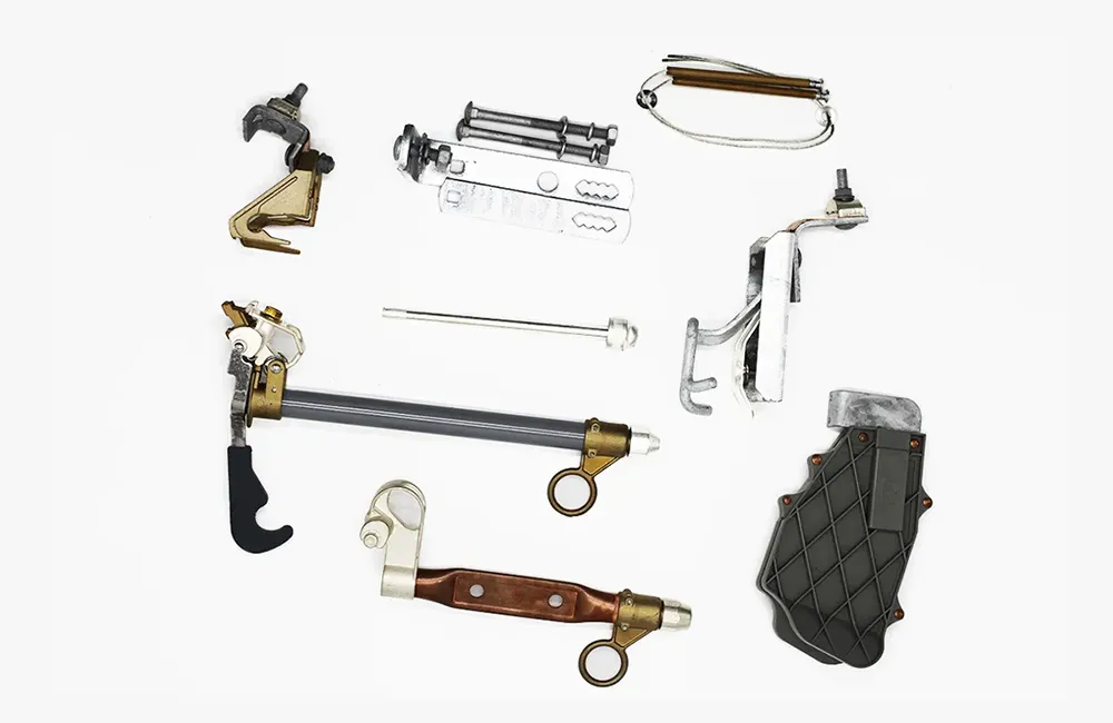
What installation context should a pole-mounted fuse cutout review include?
Pole-mounted fuse cutouts sit at the intersection of protection design and line construction. The device must fit the pole hardware plan, support conductor routing, allow fuse link replacement, and still meet the electrical class defined by the network study.
Split the review into mechanical and electrical envelopes:
| Envelope | Examples of inputs | Typical reviewer |
|---|---|---|
| Mechanical / installation | Pole class, banding, bracket type, conductor approach | Line designer / construction lead |
| Electrical / protection | Line voltage, continuous current, interrupting duty, fuse link plan | Protection engineer |
Important: Installation context is not a substitute for protection coordination. Confirm fuse-link speed and curve against the approved protection study. Source context: IEEE C37.41.
How do pole class and mounting hardware drive selection?
Pole class and banding practice determine which mounting bracket geometry is acceptable in the field. A cutout spec that lists only kV and amperes but omits bracket option forces the construction contractor to improvise—a common source of rework.
Record these hardware inputs on the drawing or RFQ:
| Hardware input | Why it matters |
|---|---|
| Pole material and class | Defines bending and banding limits |
| Bracket type (with/without factory bracket option) | Matches supplier accessory list |
| Mounting height and orientation | Affects access and dropout visibility |
| Adjacent equipment | Arresters, switches, or transformers sharing the pole |
When owners standardize on a bracket family, reference that standard explicitly so bidders do not substitute unequal hardware.
How should conductor orientation be planned at the cutout?
Conductor orientation controls mechanical load on the fuse tube, insulator, and terminals. The plan should show approach direction, phase sequence, jumper lengths, and whether the cutout is line-side or load-side relative to the protected equipment.
Poor orientation can produce binding during dropout, uneven terminal stress, or blocked visibility of the open position indicator.
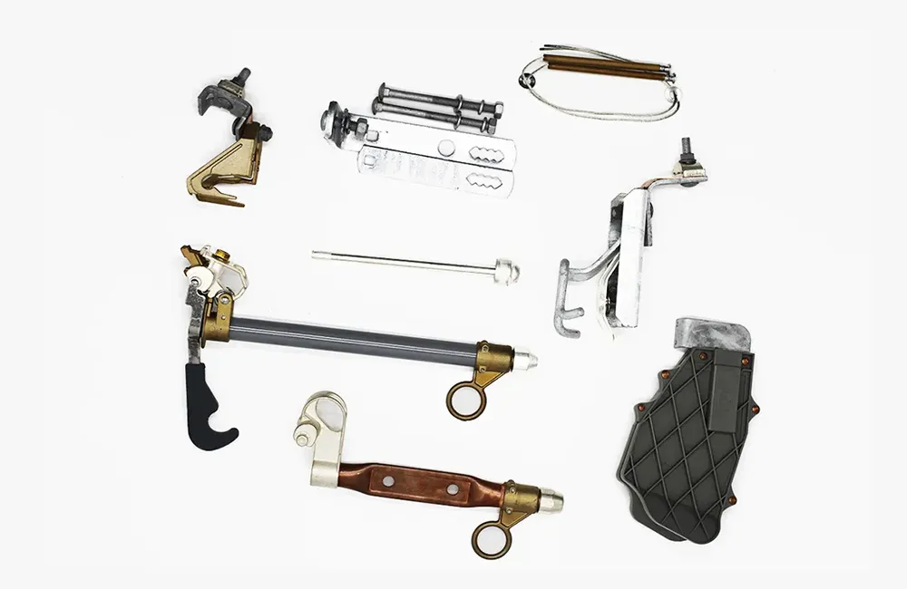
Align the drawing with the conductor size listed in the material standard. A cutout sized for smaller conductors than those installed may require different terminal hardware or a revised model.
Which clearance and access factors belong in the review?
Clearance planning must reflect owner rules, equipment spacing, and the access path crews will use to replace fuse links. This article does not replace owner energized-work procedures; it records the spatial inputs that should appear before purchase.
Review checklist:
- Working space to operate the cutout handle and verify dropout position
- Separation from adjacent phases, neutral hardware, and communications attachments
- Grounding and bonding locations shown on the installation detail
- Roadway or easement sight lines if visibility from the ground is an owner requirement
Document exceptions when field poles differ from the template drawing. A single generic pole detail may not cover every span in the project.
How do line voltage and fault level align with cutout class?
Electrical class still anchors the specification. Rated voltage must cover the maximum system voltage for the application, and interrupting capability must exceed available fault current at the pole location.
| Selection input | Review question |
|---|---|
| Maximum line-to-line / line-to-ground voltage | Does rated cutout voltage class cover operating and temporary overvoltage context? |
| Continuous load current | Does the selected continuous rating match conductor and load duty? |
| Available fault current | Does published interrupting capability exceed the fault study value at the pole? |
Cross-check these values with the owner’s protection standard. IEEE C37.42 provides the rating vocabulary; it does not by itself prove that any offered cutout meets a project specification.
Which documents should match the ordered cutout installation?
Before release to construction, these documents should tell the same story:
| Document | Match requirement |
|---|---|
| Single-line diagram | Cutout location and orientation |
| Installation detail | Bracket, conductor approach, grounding |
| Material standard | Insulator type, hardware, fuse link family |
| Nameplate / ordering code | Model, bracket option, accessory list |
| Spare parts plan | Fuse links and critical hardware |
If procurement splits cutout and fuse link orders, both packages should still reference the same drawing revision.
When does an FSC-1-5 enquiry fit a pole-mount specification?
After installation and electrical inputs are documented, a product page can start the commercial thread. The FSC-1-5 drop-out fuse cutout page publishes, for that model only:
| Parameter (FSC-1-5 page) | Published value |
|---|---|
| Voltage class | 10–15 kV |
| Continuous current options | 100 A / 200 A / 300 A |
| Breaking current | 8 kA |
| Creepage distance | 220 mm |
| Standard cited on page | IEC 60282-2 |
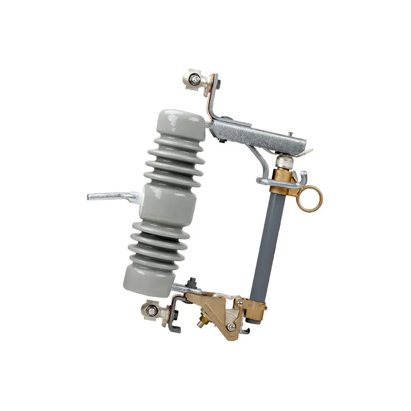
Fit Boundary
FSC-1-5 page data does not confirm pole suitability, bracket compatibility, or owner acceptance for your line standard. Confirm mounting hardware, fuse link selection, and fault/interrupting alignment before treating any model as approved.
Next step: Contact FUERTE with project parameters including pole detail, bracket preference, conductor orientation sketch, voltage/fault study reference, and requested accessories.
Pole-mounted fuse cutout questions buyers ask
What is a pole-mounted fuse cutout?
It is a dropout expulsion cutout installed on an overhead line pole to protect downstream equipment using a replaceable fuse link.
How does pole class affect mounting?
Pole class and banding practice determine which bracket and hardware package is structurally acceptable. Specify pole class on the drawing or RFQ.
What mounting hardware should be specified?
Include bracket type, banding/clamping approach, mounting height, and any owner-standard hardware part numbers rather than leaving hardware to bidder assumption.
How should conductors approach the cutout?
Show approach direction, phase order, jumper lengths, and terminal orientation on the installation detail so field crews match the engineered layout.
What clearances should planners review?
Review working space for operation and fuse replacement, separation from adjacent equipment, grounding locations, and any owner visibility requirements—using the owner’s live-work and clearance rules.
How do voltage and fault level drive selection?
Rated voltage must cover the system voltage class; interrupting capability must exceed available fault current at the pole. Continuous current must match load and conductor duty.
Which documents should match the installation?
Align the single-line diagram, installation detail, material standard, order code/nameplate data, and spare fuse link plan to the same revision.
What RFQ inputs reduce installation disputes?
Provide pole class, bracket option, conductor orientation drawing, voltage and fault data, insulator material preference, accessory list, and applicable standard references.
What is the final pole-mount selection rule?
A pole-mounted fuse cutout is ready for procurement only when the electrical duty and the physical installation can be shown on the same revision-controlled file. Confirm clearances, bracket and conductor details, fault duty, and link coordination before accepting a model number; the field drawing remains the final check.
References
- IEEE C37.41 — Design and Application of Distribution Cutouts and Fuse Mountings Used with Distribution Cutouts
- IEEE C37.42 — Design Requirements for Distribution Cutouts and Fuse Links Used with Distribution Cutouts
- IEC 60282-2 — High-voltage fuses — Part 2: Expulsion fuses including expulsion fuse-links with strikers