








When a utility engineer in Fresno reviews a transformer branch that has suddenly de-energized, the visible position of a dropped cutout can narrow the search quickly. This is an illustrative procurement scenario, not a reported field case: the important question is not simply whether the fuse melted, but whether the selected fuse link and cutout can interrupt the available fault current, limit damaging let-through energy, and leave a safe, verifiable isolation point for inspection.
Summary: A fuse cutout carries normal current through a fuse link and opens when the link melts during an overcurrent. In a typical expulsion cutout, arc gases generated in the fuse tube help extinguish the arc and the holder drops open. Current-limiting fuses use a different interruption mechanism and are selected for their peak-current and energy-let-through behavior within a specified fault-current range. For procurement, match the fuse family, voltage and current duties, interrupting capability, coordination curves, environmental requirements, and the applicable current standard; treat a dropped holder as an indication to begin an authorized isolation and inspection process, not as proof that the circuit is safe to touch.
For utilities, contractors, and electrical purchasers, understanding a fuse cutout supports specification, fault review, maintenance planning, and like-for-like replacement. The sections below explain the mechanism, the difference between expulsion and current-limiting designs, the ratings that matter, and the evidence a supplier should provide.
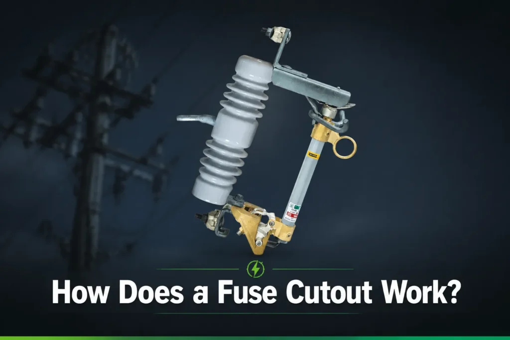
What is a fuse cutout?
A fuse cutout is an overhead distribution protection assembly that combines an insulator and contacts with a removable fuse holder or tube. Under normal conditions, current travels from the line terminal through the holder and fuse link to the lower terminal. If the link reaches its time-current operating condition, its element melts, the current path separates, and the holder can swing or drop to show that an operation occurred.
The device therefore performs two related jobs: the fuse link interrupts an abnormal current, while the open holder provides a visible indication and an isolation point after the interruption. Common applications include pole-mounted transformer primaries, lateral or branch lines, capacitor banks, and other overhead distribution equipment. A cutout is an overcurrent device; it is not a substitute for a surge arrester or for an external lightning-protection and earthing system. Eaton describes surge arresters as parallel devices that divert surge current and limit voltage, which is a different duty from clearing sustained overcurrent. For a related technical topic, see Lightning Surge Arresters: Guide to Protecting Your Electrical Systems.
How does a fuse cutout work during a fault?
In normal service, the fuse link carries the expected load without melting. When a downstream fault or severe overload raises current, the link heats according to its time-current characteristic. A high fault current can cause a rapid operation, while a lower overcurrent may take longer; the actual response depends on the link construction and rating rather than on a single universal response time.
Once the element separates, an arc forms. In an expulsion cutout, the arc-interrupting material in the tube generates gases that cool, lengthen, and de-ionize the arc. The holder then releases and drops away from the upper contact. The resulting open position helps crews identify the operated device, but it does not by itself establish that all sources are isolated or that the equipment is safe to approach.
In a current-limiting fuse, the element and filler system are designed to force current to zero before the prospective fault current reaches its unrestricted peak, reducing the let-through current and the associated I²t energy delivered to downstream equipment. This is a different physical and application concept from an expulsion cutout. A buyer should not assume that any current-limiting link can be placed in any drop-out barrel; the fuse, holder, mounting arrangement, and approved accessories must be a documented combination.
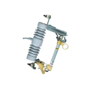
Expulsion versus current-limiting fuses
Eaton’s utility-fuse overview distinguishes expulsion fuses from current-limiting families and further separates current-limiting products into back-up, general-purpose, and full-range categories. The useful procurement distinction is the range of fault currents a fuse can clear and the amount of energy it lets through—not the product label alone.
| Decision dimension | Expulsion fuse cutout | Current-limiting fuse |
|---|---|---|
| Interruption principle | Arc is extinguished in the fuse tube using gases and de-ionization after the link separates. | Fuse construction limits the current and clears within its specified current range, reducing peak current and let-through I²t. |
| Visible post-operation state | Drop-open holder commonly provides a visible indication on overhead equipment. | May be installed in a different holder or assembly; verify whether the selected arrangement provides the required visual isolation. |
| Fault-current question | Confirm the cutout/link interrupting capability covers the available fault current at the installation point. | Confirm whether the product is back-up, general-purpose, or full-range and identify its minimum and maximum clearing duties. |
| Energy and equipment stress | Let-through depends on the link, prospective current, and interruption process; coordination remains essential. | Lower peak current and I²t can reduce fault stress, but only within the manufacturer’s tested application range. |
| Procurement check | Verify voltage class, continuous current, link curve, duty, environment, and any loadbreak accessory. | Verify fuse and holder compatibility, current range, let-through data, and the assembly’s installation instructions. |
The phrase “energy let-through” refers to the current-squared-time integral (I²t) that reaches the protected circuit before interruption. It is a selection input, not a generic performance promise. Ask for the relevant manufacturer’s curves or test data and compare them with transformer inrush, expected load, available fault current, and the withstand capability of the protected equipment. Never infer a kA value or an energy figure from a catalog title alone.
Main components and their roles
The assembly normally includes an insulator, upper and lower contacts, a fuse holder or tube, a replaceable fuse link, and a mounting bracket. Porcelain and polymeric insulators have different mechanical, weight, weathering, and handling characteristics; the project specification should state the required insulation level, creepage, pollution performance, and mechanical duty rather than relying on a material name alone.
The holder carries the link and, in an expulsion arrangement, provides the arc-interruption enclosure. Contacts and terminals establish the current path and need the specified contact pressure, conductor range, and outdoor corrosion performance. The bracket keeps the assembly aligned so that the holder can release and drop as designed. A useful fuse cutout components guide can help organize a drawing review, but the approved manufacturer’s drawing remains the controlling document for a purchase.
Ratings and coordination that determine whether it works
System voltage is only the starting point. The specification should also identify continuous current, fuse-link characteristics, available fault current at the installation, interrupting or clearing capability, insulation level, creepage, pollution and altitude conditions, mechanical duty, and any loadbreak requirement. The available fault-current range matters in both directions: a device that cannot clear the maximum prospective current is unsafe, while a current-limiting family that has a minimum clearing current may not be suitable for every lower-current fault.
Fuse-link selection uses the transformer rating, expected load, magnetizing inrush, fault-current study, and coordination with upstream reclosers, breakers, and downstream protection. Compare time-current curves so the nearest appropriate device operates first without nuisance operation during energization or normal overloads. Our ratings and selection checklist is a useful starting point; the engineer still needs the project data and the manufacturer’s curves.
Which standard applies?
Standards have scope and edition limits. IEEE’s page for C37.40-2003 describes service conditions and definitions for high-voltage fuses, distribution cutouts, fuse disconnecting switches, and accessories, but the same page marks that edition as superseded by IEEE C37.41-2016. A purchase specification should therefore name the current edition and the utility or regional requirements that apply; citing C37.40-2003 as if it were the current product standard can create an avoidable compliance gap.
Do not use surge-arrester standards as a substitute for fuse standards. IEC 60099-4 addresses metal-oxide surge arresters without gaps for AC power circuits above 1 kV, while IEC 61643-11:2025 addresses low-voltage AC surge protective devices up to 1,000 V RMS. Those documents are relevant when a project also specifies surge protection, but they do not establish a fuse cutout’s interrupting performance. A standard reference is not proof that a particular supplier is certified; request the applicable test reports, drawings, and declarations for the exact assembly.
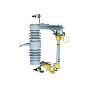
What should happen after a fuse cutout operates?
A dropped holder is a visual clue, not a work permit. Before anyone approaches, the responsible utility procedure must identify every possible source, isolate and lock out the circuit, verify absence of voltage with approved equipment, and apply grounding or other controls required for the voltage class. Only authorized, trained personnel should perform this work. A cutout without a loadbreak rating or approved tool must not be treated as a load interrupter.
After the system is made safe, use a documented inspection boundary that includes the cutout, fuse link, transformer or lateral, adjacent conductors, terminals, arrester, and signs of wildlife, vegetation, contamination, tracking, flashover, or mechanical damage. A practical replacement checklist is:
- Record the operated phase, link type, link rating, time, weather, and protection-device indications.
- Find and correct the initiating fault; do not install a larger link simply to stop repeat operations.
- Inspect the holder, tube, contacts, insulator, hardware, alignment, and mounting structure against the approved drawing.
- Confirm the replacement link is the documented type and is coordinated with upstream and downstream devices.
- Re-energize only under the utility’s approved switching, testing, and clearance procedure, then monitor for repeat operation.
Repeated operations can indicate a temporary contact, equipment failure, incorrect link selection, insufficient coordination, or an environmental condition. The remedy is a fault review and evidence-led correction, not an assumption that the cutout itself is defective.
Procurement checklist for a fuse cutout
- Define the duty: overhead transformer, lateral, capacitor bank, or another application; state whether visible isolation and loadbreak operation are required.
- Supply system data: voltage class, continuous load, inrush, available fault current, grounding arrangement, altitude, pollution, and environmental exposure.
- Choose the fuse family: compare expulsion and current-limiting options using clearing range, peak current, let-through I²t, coordination curves, and protected-equipment withstand.
- Check the documents: current standard references, type-test evidence where applicable, dimensional drawings, installation instructions, compatible link list, and replacement procedure.
- Review the supplier: ask how custom brackets, terminals, insulation materials, and environmental requirements are controlled; require the exact configuration to be identified on the quotation.
Fuerte can support a quotation review around the project voltage class, fuse-link arrangement, dimensions, and documentation. The purchaser should still provide the fault-current study and utility requirements; no supplier statement replaces that engineering check. For a broader comparison of options, see the expulsion fuse-link selection guide.
FAQs
What is a fuse cutout?
It is an overhead distribution assembly that uses a replaceable fuse link to interrupt abnormal current and commonly leaves a visible open holder after operation. The cutout’s exact interruption and switching capability depends on the fuse family, holder, rating, and approved accessories.
How does a fuse cutout work?
The link carries normal current, heats during an overcurrent, and separates when its time-current characteristic is reached. An expulsion tube then extinguishes the arc and the holder drops open; a current-limiting fuse uses a different construction to limit peak current and let-through energy within its specified range.
Why does a fuse cutout drop down?
The holder is designed to release and show that the fuse link has operated, making the affected device easier to locate. The drop is an indication, not proof of de-energization; qualified personnel must isolate, test, and ground the circuit under the applicable procedure.
Can a fuse cutout be used as a switch?
Only when the exact cutout and accessory are rated and approved for the intended loadbreak operation. A standard cutout or disconnect that lacks a loadbreak capability must not be opened under load based on appearance alone.
How do I select the correct fuse link?
Use system voltage, continuous load, transformer inrush, available fault current, fuse clearing range, and coordination curves with upstream and downstream protection. Confirm the link type and rating against the manufacturer’s approved holder and the project’s current standard; do not select by amperage alone.
What is the difference between an expulsion fuse cutout and a current-limiting fuse?
An expulsion cutout extinguishes its arc in a tube and often provides a drop-open visual indication. A current-limiting fuse is designed to reduce peak current and I²t let-through over a defined fault-current range; whether it is suitable depends on the system study, protected equipment, and the tested fuse-and-holder assembly.
References
- Eaton, “Fundamentals of utility fuses” (expulsion/current-limiting categories, fault-current range, and energy let-through).
- IEEE, C37.40-2003 information page (scope and notice that the edition is superseded by IEEE C37.41-2016).
- Eaton, “Fundamentals of surge arresters” (why surge diversion is a separate protection duty).
- IEC 60099-4:2014 (scope for metal-oxide surge arresters above 1 kV; not a fuse standard).
- IEC 61643-11:2025 (scope for low-voltage AC SPDs up to 1,000 V RMS; not a fuse standard).
The visible drop tells you where to start; the fault-current study, coordination curves, and approved isolation procedure tell you what to do next. If you are sourcing a fuse cutout for a defined overhead application, contact Fuerte with the project data and request a configuration-specific document review.