








Illustrative procurement scenario: when an electrical engineer in an industrial park investigates repeated control-panel trips after storms, the visible damage may point to a “bad arrester.” The review often finds a different root cause: the device was selected for the wrong voltage class, installed with excessive lead length, or expected to replace the building’s external lightning-protection and bonding system.
Summary: A lightning surge arrester limits transient overvoltage by conducting surge current in parallel with the protected circuit; it does not intercept lightning or absorb every surge. For AC power circuits above 1 kV, IEC 60099-4:2014 is the relevant metal-oxide arrester product and test standard. For AC low-voltage systems up to 1,000 V RMS, IEC 61643-11:2025 covers surge protective devices and updated test duties. Specify the voltage class, temporary overvoltage (TOV) duty, installation point, earthing and coordination before comparing suppliers. For a related technical topic, see Differences Between Surge Protectors and Lightning Arrestors.
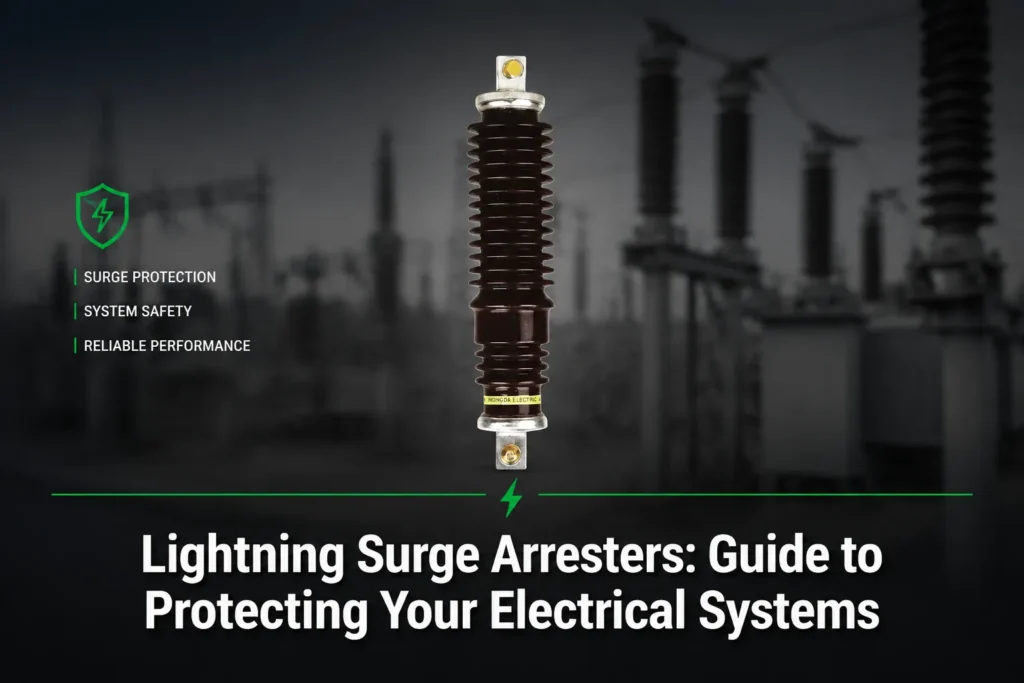
What Is a Lightning Surge Arrester?
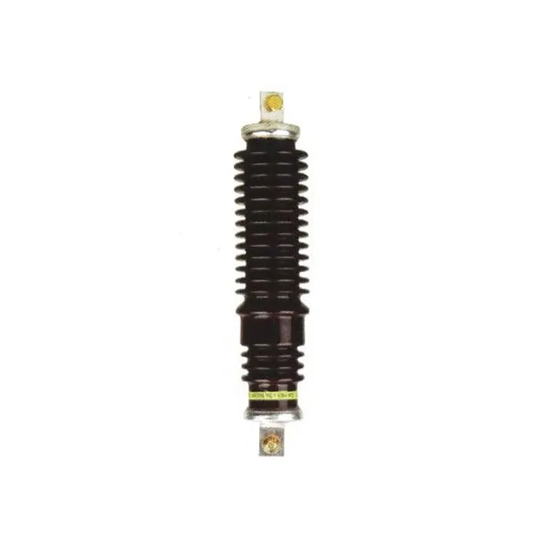
A lightning surge arrester is a shunt device that limits a transient voltage across connected equipment by providing a controlled path for surge current. Metal-oxide varistors (MOVs) remain high resistance at normal system voltage and conduct more strongly as the voltage rises. After the transient, the device returns toward its normal operating state, subject to its design limits and any damage caused by the event.
The term is used broadly in catalogs, but the purchasing decision is not a simple “lightning arrester versus surge protector” binary. Voltage class, duty, installation point, earthing arrangement and the applicable standard determine what the device is expected to do. A lightning surge arrester can protect equipment from transient overvoltage; it cannot replace air terminals, down conductors, bonding or an earthing system designed for direct-lightning current.
How Does a Lightning Surge Arrester Work?
During a surge, the arrester’s nonlinear element conducts and diverts current away from the protected insulation or electronics. The relevant outcome is the residual or protective voltage at the equipment terminals, not a promise that the surge disappears. Lightning, switching surges and temporary overvoltages are different duties; an arrester must be selected and tested for the conditions that can occur on the actual network.
Installation geometry matters. Long or routed connection conductors add inductive voltage during a fast front, so the arrester can be correctly rated yet provide a higher voltage at the equipment than expected. Keep line and earth leads as short and direct as the project instructions allow, avoid unnecessary loops, and coordinate upstream and downstream devices so their protective levels and energy duties do not conflict. The final arrangement should be checked against the manufacturer’s installation instructions and the project’s insulation-coordination study.
Why Do Electrical Systems Need More Than One Protection Layer?
External lightning protection and surge protection address related but different paths:
| Protection layer | Primary duty | What it does not prove |
|---|---|---|
| Air terminal, down conductor, bonding and earth | Intercept and route direct-lightning current around the structure where the design calls for it. | It does not establish the protective level of a power-system arrester or LV SPD. |
| Medium/high-voltage power-system arrester | Limit transient overvoltage on a power circuit at a selected line, transformer, bus or equipment location. | It does not replace external lightning protection or guarantee a protection distance. |
| Low-voltage SPD | Limit transients on AC low-voltage distribution or equipment circuits within its declared configuration. | It does not correct poor bonding, excessive lead length or an unsuitable system earthing arrangement. |
This layered view avoids a common procurement error: specifying an arrester as if it were a complete lightning-protection system. For grounding inputs and conductor details, see the surge-arrester grounding RFQ checklist.
Which Standard and Voltage Class Apply?
Above 1 kV AC: IEC 60099-4:2014 applies to gapless metal-oxide resistor-type surge arresters for AC power circuits with system voltage above 1 kV. It is a product and test standard; a reference to the standard is not, by itself, proof that a supplier or model is certified.
Up to 1,000 V RMS AC: IEC 61643-11:2025 covers low-voltage surge protective devices connected to AC systems, including direct or indirect lightning and other transient overvoltages. The 2025 edition addresses, among other duties, combined modes, T1/T2 follow-current duty, short-circuit tests, dielectric tests and clearances for electrically separated circuits. Confirm the edition and system frequency used in the project documentation.
Do not select by a nominal label alone. The data sheet and study should align continuous operating voltage (Uc/MCOV as applicable), rated voltage, discharge-current and test duty, protective level, TOV withstand, earthing configuration and the intended location. For a distribution transformer, a structured comparison of these values is more useful than a generic “heavy-duty” claim; use the metal-oxide arrester selection guide as a worksheet.
Selection and Installation Checklist
- Define the circuit: record system voltage, frequency, earthing arrangement, insulation level and whether the circuit is above 1 kV or within the LV SPD scope.
- Check TOV duty: identify credible temporary overvoltages from earth faults, switching or network conditions and compare them with the arrester’s declared capability. A device that clamps a lightning impulse is not automatically suitable for sustained TOV.
- Coordinate locations: map the service entrance, transformer, switchboard and sensitive loads. Use the manufacturer’s coordination method and the project’s insulation-coordination study; do not infer coordination from brand names.
- Control lead length: route phase and earth connections directly, keep the loop short, and follow the device installation diagram. Record the actual routing in the inspection file.
- Specify evidence: request the applicable standard edition, type-test scope, declared Uc/MCOV and protective level, TOV information, wiring diagram, environmental limits and replacement/monitoring instructions. Fuerte can review an RFQ against these inputs, but buyers should verify every value against the project design and supplied documents.
Failure Indicators and Inspection Checks
Many arresters include a visual status indicator, a disconnecting device, or a remote-contact option; the exact arrangement is model-specific. A changed indicator, operated disconnector, cracked housing, tracking, overheating marks, moisture ingress or unexplained alarm is a reason to isolate the circuit under the site’s safe-work procedure and have a qualified person inspect it. Do not treat a normal indicator as proof that the arrester has unlimited remaining capacity.
Inspection should also verify terminal tightness, conductor routing, bonding continuity, enclosure condition, environmental exposure and coordination with upstream protection. After a known surge or a disconnector operation, follow the manufacturer’s replacement and test instructions rather than attempting an improvised repair. There is no universal service-life number that can be responsibly applied without the model, duty history and environmental data.
Frequently Asked Questions
Does a lightning surge arrester stop lightning?
No. It limits transient voltage on a connected circuit by diverting surge current. Direct-lightning interception and current routing require the external lightning-protection, bonding and earthing design appropriate to the structure.
What is the difference between an arrester for a power system and an LV SPD?
The decisive distinction is voltage class and applicable standard. IEC 60099-4 covers gapless metal-oxide arresters for AC power circuits above 1 kV, while IEC 61643-11:2025 covers SPDs connected to AC low-voltage systems up to 1,000 V RMS; terminology may overlap in commercial use.
Why does TOV matter when selecting an arrester?
TOV is a temporary overvoltage that can last longer than an impulse. The arrester must withstand credible network TOV conditions without an inappropriate thermal or protective response; compare the declared TOV capability with the system study.
How do lead length and coordination affect protection?
Connection inductance can add voltage during a fast surge front, so long loops reduce the voltage margin available at the equipment. Keep conductors short and direct, then coordinate protective levels and energy duties between upstream and downstream devices using the manufacturer’s method.
What should be checked after an arrester failure indicator operates?
Use the site’s safe isolation process and have a qualified person inspect the indicator, disconnector, enclosure, terminals, bonding and wiring. Replace or test the device only as the manufacturer specifies; an operated indicator should not be reset as a substitute for diagnosis.
References
- IEC 60099-4:2014, Surge arresters—Part 4.
- IEC 61643-11:2025, Low-voltage surge protective devices—Part 11.
- Eaton, Fundamentals of surge arresters.
- IEEE C37.40-2003 page (superseded notice and scope context for related distribution equipment standards).
The useful question is not “Which arrester is strongest?” but “Which device, at which location, for which duty, with which evidence?” If you are preparing a specification or comparing offers, review the circuit data, TOV exposure, lead routing, coordination study and test documentation before requesting a final quotation. Contact Fuerte about lightning surge arrester sourcing and documentation support.