

A switchboard’s short-circuit rating does not tell a maintenance team how severe an arcing event could be at the point of work. That distinction matters when equipment is replaced, a utility supply changes or relay settings are revised. A breaker may have enough interrupting capacity while the installation still presents a substantial arc-flash exposure. OSHA’s public guidance also challenges the assumption that low voltage means little danger. For engineers and buyers, the useful question is therefore more specific than whether an assembly is adequately rated: which operating conditions, protective devices and working positions were assessed? This article explains how an arc starts, how a study estimates exposure and which records must agree before its results can support a work plan.
An arc flash is the release of thermal energy and intense light from an electric arc; pressure, noise and expelled material may accompany it. Incident energy describes thermal exposure at a stated distance, rather than the current a breaker can interrupt. IEEE 1584-2018 provides models for arc-flash calculations, with application limits that the study engineer must check. Results depend on the electrical system, equipment geometry, working distance and protective clearing time. They do not authorize energized work. Start by checking that the single-line diagram, actual protection settings and equipment arrangement match the study, then apply the relevant electrical safety procedures.
How does electrical arcing begin?
Air normally separates conductive parts. An arc can form when that separation breaks down and an ionized path carries current. Damaged insulation, contamination, deteriorated connections or accidental contact can initiate the event. A loose connection may first create localized heating and deterioration, rather than an obvious high-current fault. Identifying the initiating condition is an investigation task; an arc-flash calculation does not predict which connection will fail next.
Electrical arcing also occurs intentionally inside equipment designed to interrupt current. The controlled arc within a correctly applied interrupter is a different situation from an unintended arc inside an enclosure or across exposed conductors. The explanation of arc interruption in a vacuum circuit breaker describes that specific switching process. Its existence is not evidence that the surrounding installation is immune to an internal arc fault.
OSHA’s Electric-Arc Flash Hazards guidance treats both low-voltage exposure and incorrect assumptions about deenergization as practical concerns. Removing a hazard requires a verified work condition, not a conclusion drawn from a voltage label or an open control switch.
Why is short-circuit current different from incident energy?
Available short-circuit current is the current the supply could deliver into a fault under specified conditions. Incident energy is the thermal energy reaching a surface at a specified distance during an arcing event. The quantities answer different questions and have different units. A breaking-capacity value cannot be read as an incident-energy result.
| Quantity | What it answers | What it cannot establish alone |
|---|---|---|
| Available short-circuit current | What fault current can the network supply at this location? | Thermal exposure at the working position |
| Breaker interrupting rating | What specified fault duty can the breaker interrupt under its applicable rating conditions? | The installation’s arc-flash boundary or required work precautions |
| Incident energy | What thermal exposure is predicted at the stated distance and assessed conditions? | Probability of a fault or protection against every blast effect |
| Arc-flash boundary | At what distance does the assessed thermal exposure reach the specified threshold? | An electric-shock approach boundary |
More current does not automatically mean the worst incident-energy result. A lower arcing current can fall into a slower part of a protective characteristic. If the arc then persists longer, that longer exposure can outweigh the reduction in current. Eaton’s explanation of IEEE 1584 application describes this interaction between current and clearing time. The engineer must evaluate the applicable operating cases and protective response rather than select only the largest utility fault contribution.
What information belongs in an arc flash study?
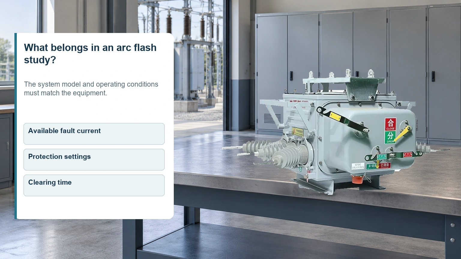
A useful arc flash study begins with a traceable system model. It needs more than a spreadsheet of nameplate ratings. The model must describe the sources feeding the fault, the impedance between those sources and the equipment, the relevant enclosure and conductor arrangement, and how protection actually clears the event.
| Record to collect | Why it matters | Useful acceptance check |
|---|---|---|
| Current single-line diagram and source data | Defines supply paths and fault contribution | Confirm normal and credible alternative operating arrangements |
| Transformer, cable and other impedance data | Affects the calculated current at the equipment | Distinguish verified records from estimates |
| Protective-device models and actual settings | Determines the response to calculated arcing current | Match installed devices and approved setting files |
| Equipment configuration and working distance | Affects how the model estimates exposure | Confirm applicability to the actual enclosure and task |
| Breaker operation and maintenance information | Supports the assumed clearing behavior | Resolve defects that could invalidate the timing assumption |
The official IEEE 1584-2018 publication page identifies the guide as a calculation method for hazard distance and incident energy and provides an errata link. The study should identify the method and version used, its applicable range and any departures or assumptions. A method for a particular AC system must not be casually extended to a different configuration, DC system or equipment arrangement.
How does protection clearing time change the result?
The relevant interval ends when the fault current is interrupted, not when a relay first recognizes it. Detection and intentional delay, output and trip-circuit operation, breaker opening and arc interruption all belong in the assessment where applicable. Describing a relay as “instantaneous” does not make the complete fault-clearing process take zero time. Eaton’s incident-energy explanation identifies working distance, voltage, available fault current and clearing time as study inputs.
Protection coordination also serves continuity of supply. Delaying an upstream device can preserve selectivity, but the effect on exposure must be checked at the relevant equipment. The article on coordinating breaker ratings and protection explains why equipment duty and protective settings should be reviewed together. Changing settings simply to obtain a smaller calculated value can create a different protection problem.
A study that assumes prompt operation also depends on equipment condition. A documented setting is insufficient if a trip supply, mechanism or other part of the clearing chain cannot perform as assumed. The discussion of vacuum circuit breaker maintenance planning helps connect service records with the assumed protective response. Maintenance information should be discussed with the study engineer rather than treated as unrelated paperwork.
Which changes should trigger a study review?
A new utility fault level, transformer replacement, altered feeder routing, additional generation or a changed bus arrangement can affect the model. Revised relay settings or a replacement protective device can affect clearing time even if the main circuit looks unchanged. A review should ask which assumptions changed and which locations need recalculation.
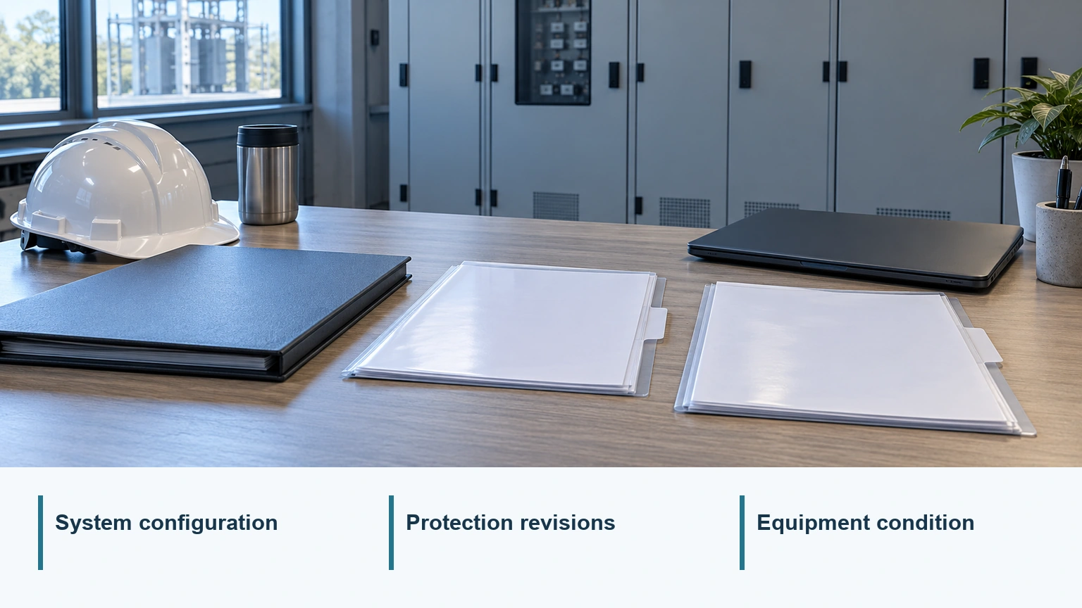
A practical handover retains the approved diagram revision, setting file, calculation report and equipment identifiers. If one record changes, the owner can then trace the consequences. This is more useful than receiving an isolated label with no way to determine which network arrangement it represents.
Arc-resistant construction addresses a different question. An assembly’s tested performance depends on its classification and installation conditions, including the configurations covered by the test. It does not eliminate arc initiation or establish permission for energized work. The discussion of assembly internal arc faults distinguishes containment measures from measures that reduce arc duration.
What else do readers ask about arc flash?
What is an arc flash?
It is the thermal and light release associated with an electric arc. The event may also produce pressure, sound and expelled material. Thermal incident-energy calculations do not quantify every possible injury mechanism.
How does electrical arcing start?
It starts when current establishes a conductive path through an insulating gap. Insulation damage, contamination and deteriorated or disturbed connections are possible initiating conditions; the specific cause requires investigation.
Can an arc flash happen without a bolted short circuit?
Yes. A bolted fault represents a solid conductive connection with negligible fault impedance. An arc carries current through an ionized path and can have a different current magnitude and protective response.
What information is needed for an arc flash study?
Typically, current network diagrams, source and impedance data, installed protective devices and settings, equipment geometry, working distances and operating cases are needed. The engineer specifies the exact inputs and records uncertainties.
How does clearing time affect incident energy?
With other conditions unchanged, a longer sustained arc generally increases thermal exposure. The study uses clearing time at the calculated arcing current, which may differ from the time at a bolted-fault current.
Does arc-resistant switchgear eliminate arc flash risk?
No. Its protective performance is conditional on the tested assembly and installation. It does not prevent every fault, replace an assessment or remove electrical safe-work requirements.
When should an arc flash assessment be reviewed?
Review it when system configuration, supply, equipment, protection settings or relevant work conditions change, and at the intervals required by the applicable safety program and standards. Do not assume an old label represents a modified system.
How does an arc flash study differ from a short-circuit study?
A short-circuit study establishes prospective fault currents for defined cases. An arc-flash study uses relevant electrical and equipment data, together with protection response and working distance, to estimate thermal exposure and boundaries.
References
- OSHA: Electric-Arc Flash Hazards and associated employer guidance.
- IEEE 1584-2018: Guide for Performing Arc-Flash Hazard Calculations, publication and errata information.
- Schneider Electric Electrical Installation Guide: Protection against assembly internal arc faults.
- Eaton: Arc energy reduction and incident-energy study inputs.
- Eaton: Exploring IEEE 1584 updates and time-current characteristics.
Summary
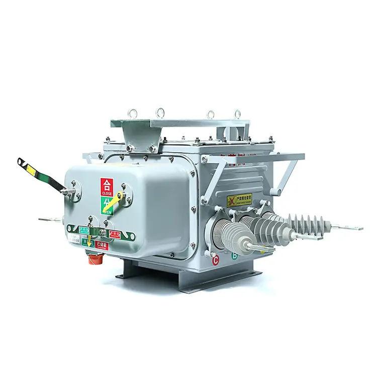
An arc-flash assessment is only as useful as its description of the installed system and the conditions under which people work. Begin with the supply arrangement and equipment records, then check the protective response at the relevant arcing currents. Keep interrupting capacity, thermal exposure and shock protection as separate decisions. Before accepting revised labels, establish which diagram, settings and maintenance assumptions support them; before work, establish the required safe condition through the site’s approved procedures. Fuerte’s ZW20 outdoor vacuum circuit breaker product information is one equipment reference for a distribution project, while the site’s system study and safety assessment remain separate responsibilities. Request the relevant equipment documentation early so it can be evaluated within that wider engineering review.