Electrical parameters
Confirm rated voltage, current, frequency, short-circuit duty, insulation levels and operating sequence.


Looking for a reliable manufacturing partner? Let us help you scale your business.
Contact SalesLooking for a reliable manufacturing partner? Let us help you scale your business.
Contact SalesLooking for a reliable manufacturing partner? Let us help you scale your business.
Contact SalesLooking for a reliable manufacturing partner? Let us help you scale your business.
Contact SalesLooking for a reliable manufacturing partner? Let us help you scale your business.
Contact Sales
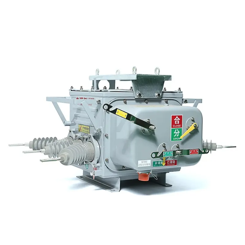
Vacuum circuit breaker
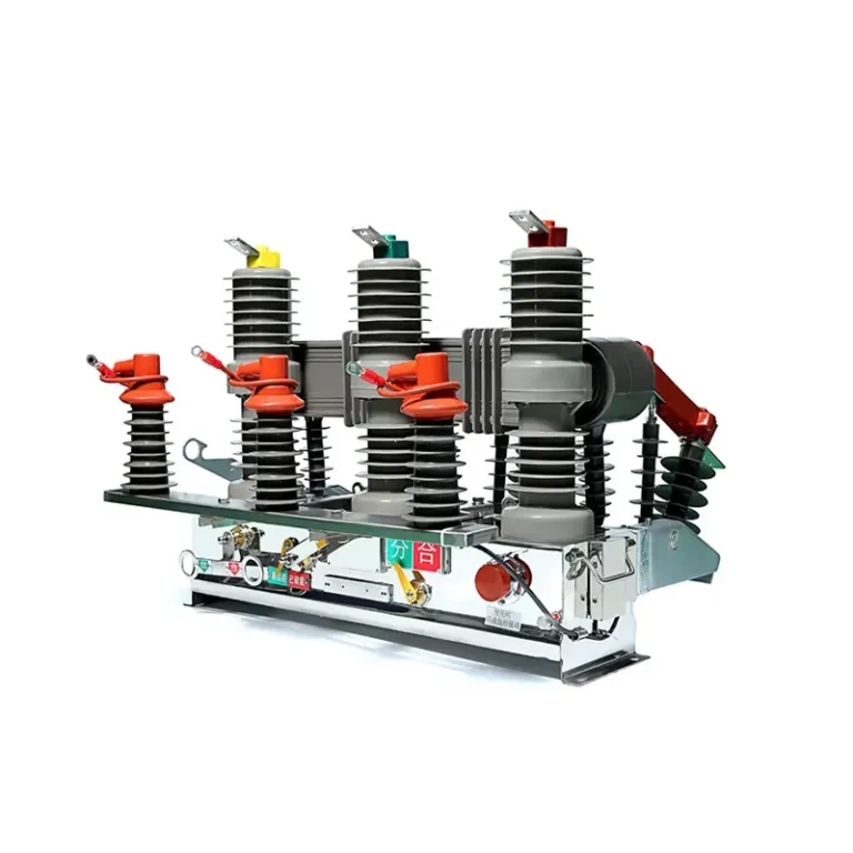
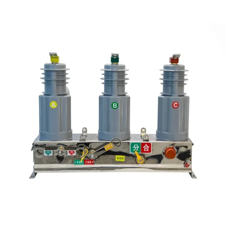
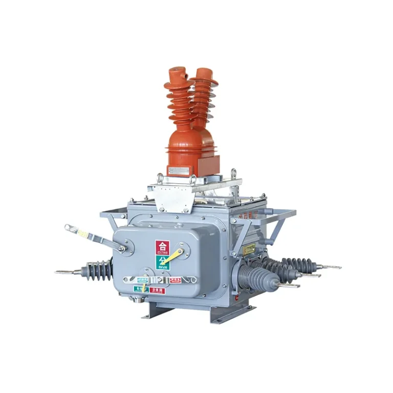
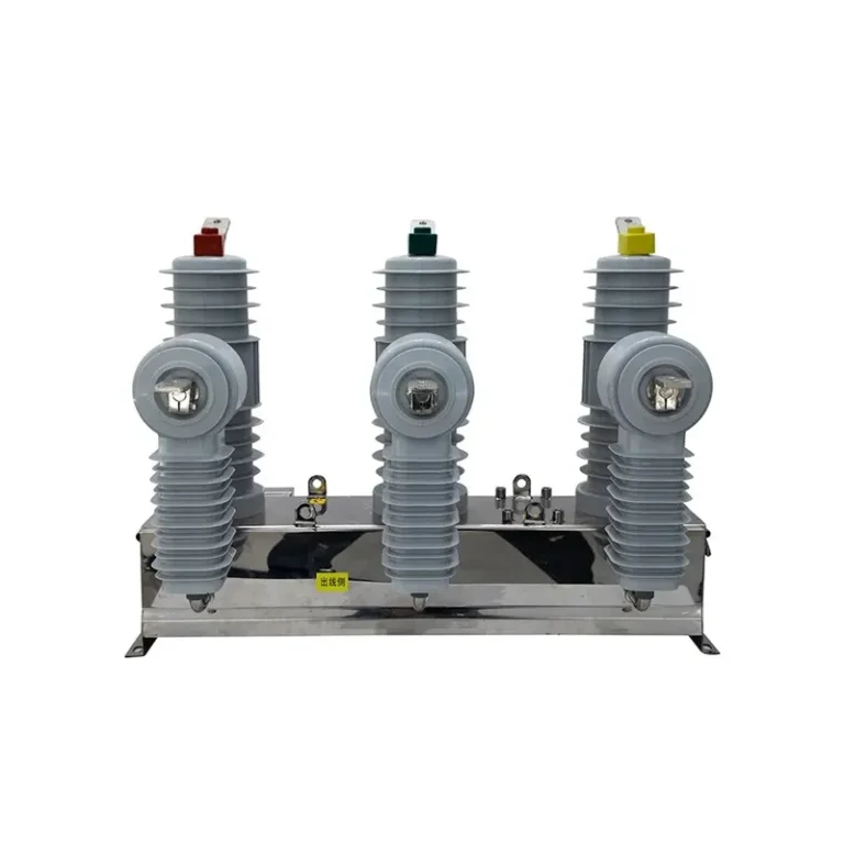
ZW20-12/630-20 Vacuum Circuit Breaker is presented for medium-voltage switching and protection projects. The authenticated supplier source provides product-specific construction notes and technical rows where published; use the exact model and installation duty for final selection.
The page keeps the supplier’s model identity and source tables where available. Confirm the applicable IEC/GB standard, rated voltage, current, breaking capacity and project acceptance documents before ordering.
Request a configuration reviewBrowse vacuum circuit breakers
Published technical data
Use the source data below as the starting point for engineering review. Keep voltage class, continuous current, short-circuit duty, operating mechanism and installation environment together when selecting a breaker.
| No | Descriptions | unit | Standard parameter values | ||
|---|---|---|---|---|---|
| 1.1 | Vacuum Circuit Breaker | ||||
| 1.1.1 | Model No | ZW20-12 | |||
| 1.1.2 | Switching structure | Transformer form | External or internal | ||
| Insulating Material | A:Epoxy resin outsourced silicone rubber | ||||
| B:Outdoor epoxy resin | |||||
| 1.1.3 | Insulating and extinguishing media | SF6, Vacuum | |||
| 1.1.4 | Rated Voltage | kV | 12 | ||
| 1.1.5 | Rated Current | A | 630 | ||
| 1.1.6 | Rated cable charging and breaking current | A | 20 | ||
| 1.1.7 | Rated short-circuit breaking current | kA | 12.5, 16, 20 | ||
| 1.1.8 | Temperature rise test current | 1.1Ir | |||
| 1.1.9 | Rated frequency 1 min withstand voltage | To earth/Between | kV | 42 | |
| Across the base | kV | 48 | |||
| 1.1.10 | Rated lightning impulse withstand voltage(1.2/50μs)Peak value | To earth/Between | kV | 75 | |
| Across the base | kV | 85 | |||
| 1.1.11 | Rated short-time withstand current and duration | kA/s | 20/3 | ||
| 1.1.12 | Rated peak withstand current | kA | 50 | ||
| 1.1.13 | Rated short-circuit breaking current | kA | 20 | ||
| 1.1.14 | Rated short-circuit closing current | kA | 50 | ||
| 1.1.15 | Main circuit resistance | μΩ | 80 | ||
| 1.1.16 | Mechanical stability | times | ≥10000 No load | ||
| 1.1.17 | Minimum creepage distance for external insulation | mm | 372 | ||
| 1.1.18 | Rated short-circuit breaking current breaking times | times | ≥30times | ||
| 1.1.19 | Closing and opening not synchronized | ms | ≤2 | ||
| 1.1.20 | Contact closing bounce time | ms | ≤2 | ||
| 1.1.21 | Partial discharge(1.1Ur) | pC | ≤20 | ||
| 1.2 | Operating Mechanism | ||||
| 1.2.1 | Type or model of actuator | Spring or permanent magnet mechanism | |||
| 1.2.2 | Operating Method | Motorized with manual operation | |||
| 1.2.3 | Motor Voltage | V | Conventional DC220 | ||
| 1.2.4 | Auxiliary contact capacity | DC24V、10A | |||
| 1.2.5 | DC resistance of telecommunication circuit | After 100times operations<1Ω | |||
| 1.3 | Transformer combination mode | Includes current transformers, electronic zero sequence voltage transformers, and electromagnetic voltage transformers or other models.. | |||
| 1.4 | Current Transformer | ||||
| 1.4.1 | Rated current ratio | (1) Phase current: 600A/5A (2) Zero sequence current: 100A/1A | |||
| 1.4.2 | Accuracy Level | (1) phase current: protection class 5P10 (2) Zero sequence current: use 100A/1A Protection Class 10P30. | |||
| 1.4.3 | Implementation method | Electromagnetic | |||
| 1.4.4 | Temperature range | -40℃~70℃ | |||
| 1.5 | Electromagnetic voltage transformers | ||||
| 1.5.1 | Rated Voltage Ratio | Zero sequence voltage: (10kV/)/( 6.5V/3) | |||
| 1.5.2 | Accuracy Level | Zero sequence voltage: 3P level | |||
| 1.5.3 | Temperature range | -40℃~70℃ | |||
| 1.5.4 | Partial discharge | Pc | ≤20 (1.1Um) | ||
| 1.5.5 | Load Impedance | ≥2MΩ | |||
| 1.6 | Electromagnetic voltage transformers (external) | ||||
| 1.6.1 | Quantities | Pc | 1 or 2 optional | ||
| 1.6.2 | Rated Voltage Ratio | Line voltage measurement: 10kV/0.1kV Supply voltage: 10kV/0.22kV | |||
| 1.6.3 | Accuracy level | Measuring voltage winding: 0.5 level Supply voltage winding: 3 levels | |||
| 1.6.4 | Capacity (VA) | Measuring voltage winding: ≥10VA Supply voltage winding: long-term capacity ≥ 50VA, short-time capacity ≥ 300VA/30s | |||
| 1.7 | Mechanical property | ||||
| 1.7.1 | contact opening distance | mm | 9±1 | ||
| 1.7.2 | contact overtravel | mm | 3.5±0.5 | ||
| 1.7.3 | Average closing speed | m/s | 0.4-0.8 | ||
| 1.7.4 | Average gate opening speed | m/s | 1.0-1.4 | ||
| 1.7.5 | Closing time | mm | ≤60 | ||
| 1.7.6 | Split time | Ms | ≤ 45 | ||
| 1.7.7 | Closing Bounce Time | Ms | ≤2 | ||
| 1.7.8 | Three-phase switching non-synchronous | Ms | ≤2 | ||
| 1.7.9 | Interphase center distance | mm | 280 ±1.5 | ||
| 1.8 | Enclosure protection class | Not less than IP65 | |||
| 1.10 | Box Material | 304 or hot rolled steel | Support for surface treatment | ||
| 1.11 | Secondary equipment | ||||
| 1.11.1 | Intelligent Control Terminal | Support remote local, three protection, three remote, reclosing, SOE, can also be equipped with the statute of the communication connection backstage real-time monitoring, adjusting, issuing fixed value and other configurations, other requirements to inform when ordering | One or two times are connected by aviation plug-in, without external wiring. |
Values shown are transcribed from the target listing where the authenticated source publishes them. Confirm the exact model row, unit, test condition and revision before using any value in a purchase specification.
Selection checklist
Configuration and supply boundary
The supplier listing identifies a vacuum-circuit-breaker model family. State the exact model code and switching arrangement so the quotation does not mix ratings or accessories from another series.
Confirm rated voltage, current, frequency, short-circuit duty, insulation levels and operating sequence.
Specify stored-energy mechanism, motor and coil voltages, auxiliary contacts, interlocks and local/remote control.
Confirm pole arrangement, insulation housing, enclosure, altitude, temperature, pollution and installation interface.
Quantity, packing, delivery schedule, private label and project documents remain subject to technical review and quotation.
Company scale
FUERTE lists 1985 as its founding year, 220+ employees and a 36,000 m² built-up area. These supplier-published figures provide context for manufacturing and project support.
1985
Supplier-published company history
220+
Published workforce scale
36,000 m²
Published manufacturing footprint
OEM
Subject to technical review
OEM & ODM capability
FUERTE’s published OEM and ODM scope includes voltage/current adaptation, mounting hardware, nameplates, packaging and shipping marks.
Electrical configurationReview voltage class, current rating, insulation levels and service conditions.
Mechanical interfaceConfirm pole structure, operating mechanism, fittings and mounting dimensions.
Project documentationState drawings, wiring, marking, packing, shipping marks and acceptance-document requirements before quotation.

Frequently asked questions
Start with rated voltage, continuous current, short-circuit breaking capacity, insulation levels, operating sequence and installation environment.
No. Confirm the exact model code and source table. Do not transfer ratings, dimensions or accessories from a similar-looking series.
FUERTE publishes adaptation of mounting hardware and project specifications as an OEM/ODM scope. Availability depends on technical review.
State model, rated voltage, current, breaking duty, mechanism and coil voltages, mounting interface, quantity, destination and required documents.
Configuration review
Provide rated voltage, current, breaking duty, insulation levels, mechanism, dimensions, mounting details, quantity, destination market and required documents.
Interested in this product? Fill out the form below and our sales team will get back to you within 24 hours.
Please feel free to leave a message for consultation. We will offer you more service options.