








When utility engineer Daniel Ruiz in Cebu City reviewed a feeder trip after a coastal thunderstorm, he checked the controller record and ordered the line re-energized. The breaker opened again within seconds, leaving a flashover trace across contaminated insulation. The interrupter was not simply “bad”: selection had overlooked pollution severity, lightning protection, creepage distance, and the 33 kV system’s highest voltage.
Summary: A pole-mounted vacuum circuit breaker must be specified as a complete installation—not just an interrupter. For a 33 kV network, that commonly means equipment in a 36 kV or 40.5 kV class, subject to the applicable regional standard and system maximum voltage. Confirm interrupting duty, IEC/IEEE test basis, insulation coordination, controller power, communications, structure loading, access, and isolation points before purchase.
A pole-mounted breaker places medium-voltage switching and fault interruption beside an overhead feeder. Vacuum interrupters extinguish the arc in a sealed bottle; bushings, an enclosure, a mechanism, sensors, surge protection, and a controller make the assembly usable outdoors. Buyers comparing an outdoor vacuum circuit breaker should evaluate the breaker, controls, mounting structure, and protection scheme together.
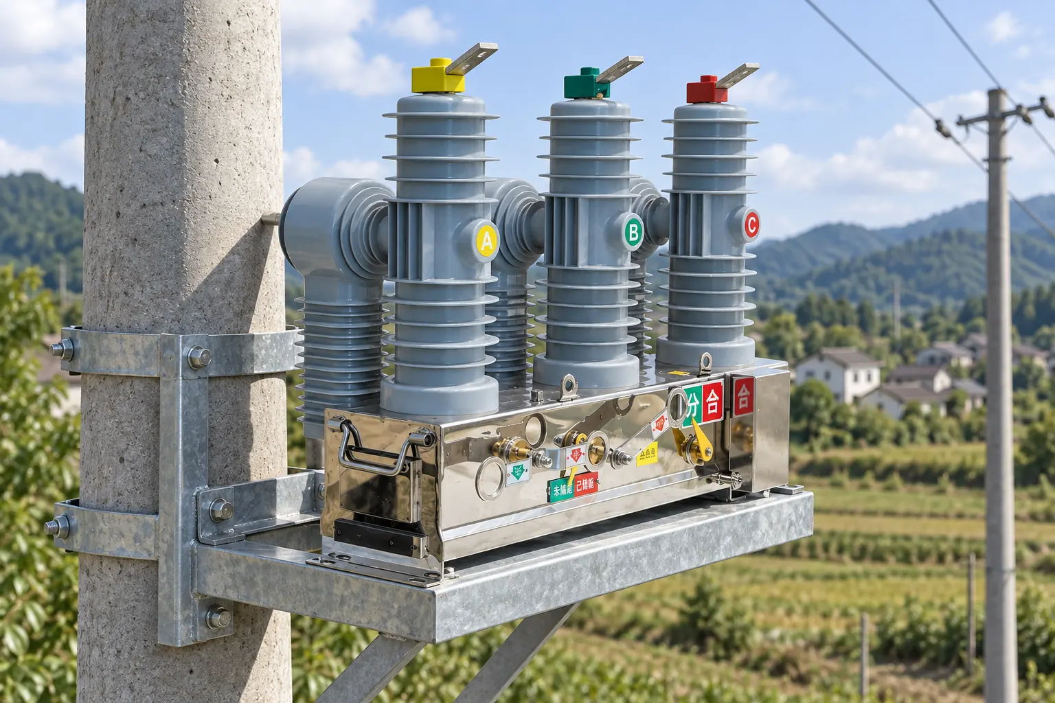
How does pole-top switching support distribution automation?
During a fault, current transformers or sensors feed a protection relay or feeder terminal unit (FTU). Its logic issues a trip command, the mechanism separates the vacuum contacts, and the controller records current, time, and operation count. Depending on the scheme, automatic reclosing may restore service after a transient fault or lock out after a programmed sequence. IEEE C37.60 and IEC 62271-111 address automatic circuit reclosers; a breaker applied without automatic reclosing may instead be evaluated primarily under IEC 62271-100 or the relevant IEEE circuit-breaker standards. Procurement documents should state which device function is required.
Remote operation needs more than a radio. The chain includes auxiliary power, battery supervision, interlocks, close and trip circuits, position indication, an RTU or FTU, communications, and SCADA. Common protocols include DNP3 and IEC 60870-5-104; IEC 61850 may suit compatible architectures. Agree cybersecurity ownership, time synchronization, event storage, and communications-failure behavior before factory acceptance testing.
| Configuration | Best fit | Operational value | Trade-off to check |
|---|---|---|---|
| Local manual control | Low-operation rural spur | Simple control architecture | Longer patrol and restoration time |
| Remote trip/close | Supervised feeder switching | Faster dispatch response | Control power, telecoms, and interlocks |
| Automatic reclosing | Overhead feeders with transient faults | Potentially restores supply without a crew visit | Protection coordination and lockout policy |
| Sectionalizing scheme | Multi-device automated feeder | Isolates a smaller faulted segment | Settings, latency, and device interoperability |
The nameplate short-circuit rating must exceed the calculated duty at the installation point with the required margin and X/R assumptions. A buyer should distinguish rated short-circuit breaking current from making current, short-time withstand, and operating sequence; the related guide to vacuum circuit breaker breaking-capacity specifications explains why a single “kA” value is insufficient.
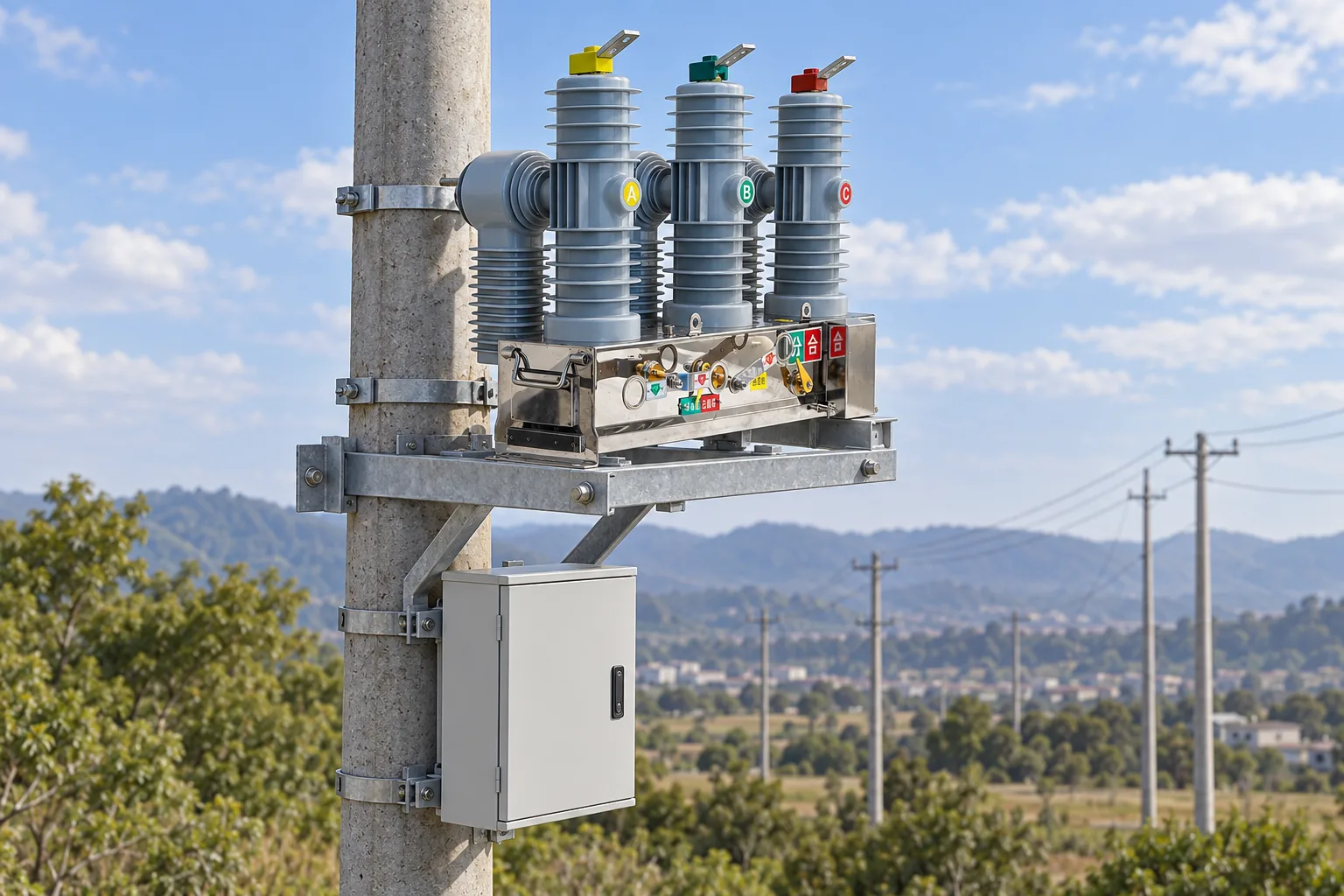
How should insulation and clearances be matched to the installation?
Outdoor insulation coordination starts with the system’s highest voltage for equipment, lightning impulse withstand, power-frequency withstand, earthing method, surge-arrester location, altitude, and environmental severity. IEC 60071-1 provides the principles and definitions; it does not turn a generic clearance into a universal installation value. Above the standard reference altitude, reduced air density can require correction factors or larger external clearances. Salt, industrial dust, condensation, and bird activity can also make creepage performance decisive even when dry-air clearance appears adequate.
For a nominal 33 kV feeder, do not assume that “33 kV” on a quotation resolves the insulation question. Markets may specify 36 kV or 40.5 kV rated equipment, with impulse levels and clearances selected by the governing utility standard. The project’s one-line diagram, insulation study, and local rules should decide whether a 33 kV outdoor vacuum circuit breaker is correctly coordinated with arresters, transformers, cable terminations, and adjacent line hardware.
| Application dimension | Questions to resolve | Evidence to request |
|---|---|---|
| 12–15 kV distribution | Fault duty, reclose sequence, sensor ratio, pole loading | Type-test basis, drawings, protection data |
| 24–27 kV distribution | External insulation, arrester coordination, connector interfaces | Insulation levels and interface dimensions |
| 33 kV system | 36/40.5 kV class, BIL/LIWV, phase spacing, structure strength | Approved data sheet and insulation-coordination review |
| Coastal or polluted site | Creepage, housing material, sealing, corrosion protection | Environmental test reports and maintenance guidance |
| High-altitude site | Altitude correction and thermal limits | Manufacturer’s derating or corrected withstand data |
Safety clearances are jurisdiction- and geometry-specific. IEEE C2, the National Electrical Safety Code (NESC), addresses US supply-station and overhead-line clearances; utility standards may be stricter. NFPA 70E covers work practices and arc-flash risk, not NESC line-clearance design. Before maintenance, crews need an approved switching order, isolation, absence-of-voltage verification, required grounding, and control-circuit disabling.
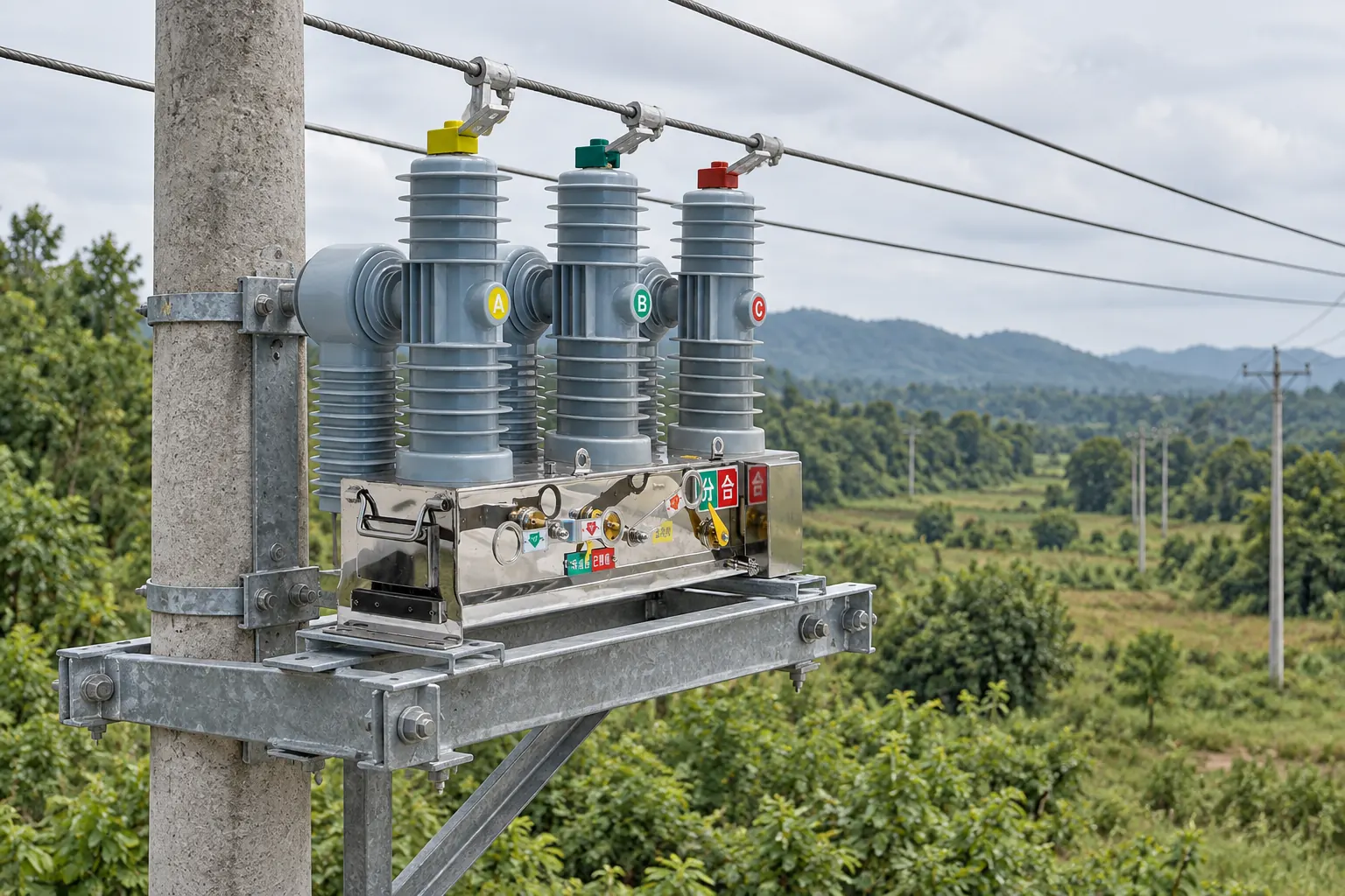
How do interface and maintenance decisions affect lifecycle cost?
Hidden costs often sit at the interfaces. Engineering hours rise when sensors do not match the relay, the controller lacks the utility protocol, the frame conflicts with crossarms, or auxiliary power cannot support heaters and charging. Field rework, another outage, bucket-truck time, and repeated protection studies can outweigh a modest purchase-price difference.
Use an illustrative lifecycle comparison, not an unsupported payback claim. If remote isolation saves two dispatches per year, multiply documented dispatch cost by two, then subtract telecoms, battery allowance, controller testing, and cybersecurity support. Add outage value only from an accepted owner model; the result then remains auditable.
What should buyers confirm before ordering?
- Provide system voltage, maximum voltage, frequency, continuous current, calculated fault duty, grounding method, duty cycle, and protection philosophy.
- Define altitude, temperature range, pollution severity, corrosion exposure, seismic or wind loading, pole material, and available working space.
- Specify local/remote functions, protocol, power supply, battery autonomy, I/O list, time synchronization, event records, and fail-safe states.
- Request standards editions, complete type-test evidence, routine-test plan, drawings, manuals, spare-parts list, and installation interfaces—not a certificate label alone.
- Review the proposed vacuum circuit breaker mounting configuration with the structural and line-design teams before release.
At this stage, Fuerte can be asked to map the buyer’s approved data sheet to a configurable offer and identify any missing interface information. The evaluation should remain evidence-led: accept ratings, environmental suitability, and compliance only when supported by the applicable drawings and test documentation for the offered model.
What does each applicable standard actually cover?
- IEC 62271-100: requirements and tests for high-voltage alternating-current circuit breakers. It is a product standard, not proof that every installation layout is safe.
- IEC 62271-111 / IEEE C37.60: requirements for overhead, pad-mounted, dry-vault, and submersible automatic circuit reclosers and fault interrupters. Applicability depends on whether the offered unit performs the covered automatic-reclosing function.
- IEC 60071-1: insulation-coordination definitions, principles, and rules. The project still needs site inputs, overvoltage assumptions, and equipment withstand values.
- IEEE C2 (NESC): safety rules for electric supply and communication lines and associated equipment in its adopting jurisdictions. Local law, utility standards, and edition adoption control.
- NFPA 70E: electrical safety-related work practices. It informs the maintenance program but does not certify the breaker or set every outdoor construction clearance.
In a tender, state the exact standard edition, rated values, test sequence, reporting language, and whether independent witnessing is required. “Designed to IEC” is not equivalent to evidence of the specified type tests. Unsupported compliance language can delay utility approval, trigger retesting, or create a contract dispute; destination-market rules and the purchaser’s approved specifications remain decisive.
Frequently asked questions
What is a pole-mounted vacuum circuit breaker?
It is a medium-voltage breaker installed on a pole or pole-top structure, using vacuum interrupters to interrupt load and fault current. A complete installation also includes external insulation, an operating mechanism, sensing and protection, control power, mounting hardware, earthing, and often communications.
Where are pole-mounted VCBs used?
They are used on overhead distribution feeders, industrial distribution networks, renewable-energy collector systems, and sectionalizing points where ground-level switchgear is impractical. The appropriate design depends on fault level, switching duty, environment, structure, and the utility’s protection philosophy.
How is a pole-mounted breaker controlled remotely?
An FTU or RTU supervises trip and close circuits, receives protection and status inputs, and exchanges commands and events with SCADA over radio, cellular, fiber, or another utility channel. Remote closing must be governed by interlocks, authorization, communications-failure behavior, and the owner’s operating procedure.
What voltage classes are available for pole-mounted VCBs?
Common medium-voltage offerings are associated with 12/15 kV, 24/27 kV, and 36/38/40.5 kV classes, but availability and terminology vary by standard and manufacturer. Select by the system’s highest voltage and insulation requirements, not nominal voltage alone.
How do I maintain a pole-mounted vacuum breaker?
Follow the model-specific manual and a condition- or interval-based program covering mechanism operation, contact-wear indication, insulation cleaning, bushing condition, enclosure sealing, corrosion, heaters, batteries, wiring, sensors, trip/close circuits, and protection tests. Review operation counters and fault records, and isolate, test, and ground the circuit under the owner’s safety procedure before physical work.
What safety clearances are needed around a pole-mounted VCB?
There is no single universal distance. Required phase-to-phase, phase-to-ground, climbing, structure, roadway, building, and working clearances depend on voltage, impulse level, conductor movement, altitude, local code, pole geometry, and the utility standard; the line designer should document them for the actual installation.
Which sources support these recommendations?
- International Electrotechnical Commission, IEC 62271-100, High-voltage switchgear and controlgear—AC circuit-breakers.
- IEEE Standards Association, IEEE C37.60, High-voltage switchgear—Automatic circuit reclosers and fault interrupters.
- International Electrotechnical Commission, IEC 60071-1, Insulation co-ordination—Definitions, principles and rules.
- IEEE Standards Association, IEEE C2, National Electrical Safety Code.
- National Fire Protection Association, NFPA 70E, Standard for Electrical Safety in the Workplace.
The durable rule is simple: specify the installation interfaces as carefully as the vacuum interrupter.
For a project-specific review, send Fuerte your single-line diagram, system maximum voltage, fault study, environmental conditions, control requirements, and pole-layout drawing. Explore the pole-mounted vacuum circuit breaker category and contact the team to confirm the applicable configuration and documentation.