








An overhead fuse cutout is a coordinated assembly, not a set of freely interchangeable parts. The mounting bracket, insulator, line and load contacts, fuse holder or tube, hinge, latch, and fuse link each have a defined interface. A tube or bracket that looks similar may not align or latch in another assembly family.
Match the complete assembly drawing, approved tube and link family, site insulation inputs, and spare-parts list before ordering. IEC 60282-2 covers requirements and tests for high-voltage expulsion fuses, but it does not make unrelated tubes, links, or brackets interchangeable.
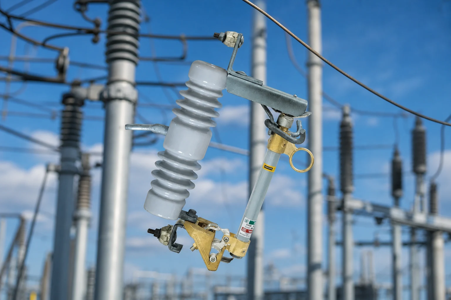
Assembly components and ordering evidence
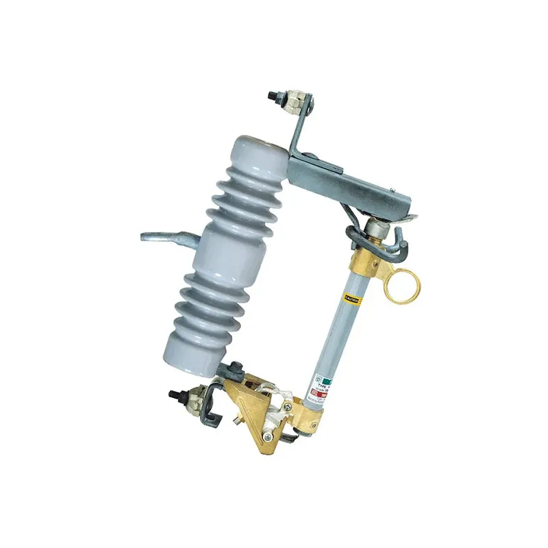
The practical part map starts at the structure and follows the electrical path. The bracket fixes the device to the pole or cross-arm; the insulator supports the line-to-ground stress; contacts and the fuse link carry current; and the tube, hinge, and latch provide the operating and visible-open functions. Treat the assembly as one coordinated design, even when individual items appear separately on a bill of materials.
| Component | Function in the assembly | Evidence to confirm before ordering |
|---|---|---|
| Mounting bracket or cross-arm adapter | Transfers mechanical loads and fixes orientation, offset, and tube swing clearance. | Structure drawing, bolt pattern, and manufacturer general arrangement. |
| Insulator | Provides the insulated support between the energized path and the structure. | Owner insulation requirements, pollution assumptions, material option, and interface drawing. |
| Upper and lower contacts | Make the series current path through the installed link and maintain the intended alignment. | Contact arrangement, conductor clamp details, and exact model drawing. |
| Fuse holder or expulsion fuse tube | Holds the link and provides the product-defined path for expulsion during operation. | Approved tube/link family, exhaust orientation, and replacement-part number. |
| Hinge and latch | Define the pivot, retain the tube in service, and allow the tube to drop after link operation where the design provides that indication. | Hinge side, latch condition, gravity orientation, and inspection procedure. |
| Expulsion fuse link | Is the replaceable current-carrying element that operates under the specified overcurrent conditions. | Link type, coordination study, and manufacturer approval for the tube. |
For the electrical inputs that sit behind the part map, use the fuse cutout ratings and selection guide. It is safer to carry the model number and drawing revision through every quotation than to assume a visually similar component is a substitute.
Mounting geometry and insulation inputs
Mounting is a mechanical-interface decision. Confirm the pole or cross-arm attachment, standoff, conductor approach, and tube drop clearance. A bracket that fits the structure can still misalign the upper and lower contacts if its offset or rotation differs from the cutout drawing.
The insulator is a separate specification item because it supports voltage stress while the contact set carries current. Material choice and creepage inputs depend on the owner’s insulation coordination and site environment. IEC 60282-2 is the relevant expulsion-fuse standard context; it should be read with the project specification rather than used as a shortcut for an unverified creepage value.
Ask for one controlled general-arrangement drawing showing the bracket, insulator neck, conductor terminals, contact line, and hinge axis. That document is the quickest way to expose a mixed-family quotation before fabrication.
Current path, tube operation, and visible opening
The fuse holder or tube captures the approved link. In normal service, current passes from the line terminal through the upper contact, link, lower contact, and load terminal. The hinge and latch keep the tube aligned and closed while the insulator and bracket hold the assembly in its designed position.
When the link operates, the tube follows its published expulsion and drop-out behavior. The hinge may let the tube fall clear, creating a visible open indication, but that indication does not replace the owner’s isolation and grounding procedure. A field crew should never infer that the line-side contact is de-energized from the tube position alone.
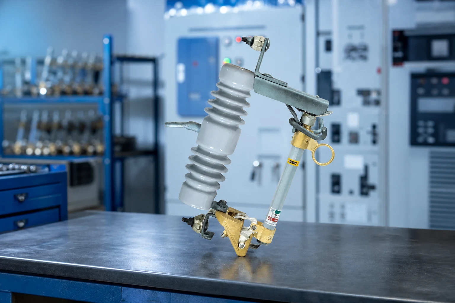
For the sequence of link operation and tube movement, see how a fuse cutout operates. Keep that operating explanation separate from the component boundary: the tube is not the fuse, and a hinge or contact kit is not automatically interchangeable across product families.
Inspection findings and replacement boundaries
Inspection should identify a failed or damaged part without turning a field observation into an unsupported diagnosis. Look for cracked or contaminated insulation, tracking or flashover marks, bent or loose mounting hardware, a latch that will not seat, a hinge that binds, damaged contact surfaces, a distorted tube, or a spent link. Record the assembly position, model, drawing revision, and photographs before removing parts.
| Observation | Component boundary to check | Replacement decision |
|---|---|---|
| Tube does not latch or drops unexpectedly | Hinge axis, latch, contact alignment, and bracket orientation. | Hold the assembly out of service until the exact drawing and inspection procedure authorize a part-level repair or complete replacement. |
| Visible tracking, cracks, or severe surface damage | Insulator surface and adjacent hardware; also inspect clearances and contamination. | Do not assume cleaning restores the part. Follow the owner’s electrical inspection and replacement criteria. |
| Link operated with a sound-looking tube | Fuse link type and coordination, holder, contacts, and tube interior as accessible under the procedure. | Replace only with the approved link and any parts named by the manufacturer; investigate the downstream fault before re-energizing. |
| Hot or discolored termination | Conductor clamp, contact pressure, hardware, and alignment. | Verify torque and contact condition against the model documentation; do not infer a rating or service-life limit from color alone. |
The fuse cutout field identification guide can help a procurement team label photographs and drawings consistently. The replacement boundary is the exact catalog assembly and approved spare list, not whatever individual part appears easiest to remove.
RFQ details and IEC 60282-2 scope
An RFQ should state the system context, continuous-current requirement, insulation inputs, conductor and structure interfaces, insulator material option, tube and hinge family, contact arrangement, approved fuse-link family, applicable standard, drawing revision, spare-parts scope, and quantity. Ask the supplier to identify what is included in the cutout package and what must be supplied by the structure contractor.
IEC 60282-2 is a product standard for high-voltage expulsion fuses and their tests; it is not a blanket certification of every configured installation. Project acceptance still depends on the specified system, the exact design, and the destination market’s rules. Avoid marketing language that turns a standards reference into an unsupported rating, certification, or safety promise.
Where the published configuration is relevant, review the FSC-1-1 drop-out fuse cutout product page for the manufacturer’s model-specific options. Do not copy any value from that page to another catalog number without its own drawing and technical confirmation.
Common component questions
Which parts are included in a fuse cutout?
The core set is the mounting bracket, insulator, line and load contacts, fuse holder or tube, hinge, latch, and approved fuse link. Conductor terminals and structure hardware complete the installation interface. Confirm the names against the exact manufacturer’s drawing.
Can a fuse tube be reused after link operation?
The tube or holder houses the replaceable fuse link and supports the product-defined operating path; it is not the fuse itself. A tube may remain usable after a link operates, but that decision requires the manufacturer’s inspection and spare-parts criteria.
Why can a secure bracket still misalign the cutout?
Offset, rotation, bolt pattern, or tube-drop clearance can differ between assembly families. A bracket mismatch can misalign contacts or prevent the latch from seating even when the pole attachment appears secure. Check the general-arrangement drawing before approving a substitute.
Which parts need inspection after a link operates?
Start with the approved link type and inspect the tube, contacts, hinge, latch, insulator, and mounting hardware. Replace only the parts allowed by the exact model documentation, and resolve the downstream fault under the owner’s isolation procedure before re-energizing.
Does IEC 60282-2 cover the complete installation?
No. IEC 60282-2 defines requirements and tests for high-voltage expulsion fuses; it does not replace project-specific insulation coordination, structure design, installation controls, or local compliance review. Cite the standard only for the scope it actually covers.
Verify the assembly before release
Fuse cutout selection starts with a component map, not a product photograph. Name the bracket, insulator, contacts, holder or tube, hinge, latch, and link; then connect each name to a drawing, an interface, and an inspection boundary. This check can reveal a link, tube, or bracket that is individually plausible but belongs to the wrong family. Use IEC 60282-2 for the expulsion-fuse requirements and test scope, while the owner specification governs insulation, structure, isolation, and acceptance. Before release, compare the complete assembly drawing, approved spare list, and field replacement procedure. The right question is not whether one part looks interchangeable, but whether the entire current path, mechanical path, and service sequence remain the same. That discipline can reduce rework and make the quotation auditable.
Standards and manufacturer references
- IEC 60282-2, High-voltage fuses – Part 2: Expulsion fuses, official IEC Webstore publication page.
- IEEE C37.41-2016, official IEEE standard page for distribution cutout and fuse-device test requirements.
- Hubbell Power Systems, manufacturer reference for industry cutout terminology and product documentation.
For a model-specific quotation and spare-parts review, see the FUERTE fuse cutout range and contact the team with the assembly drawing, model number, and site interface details.