
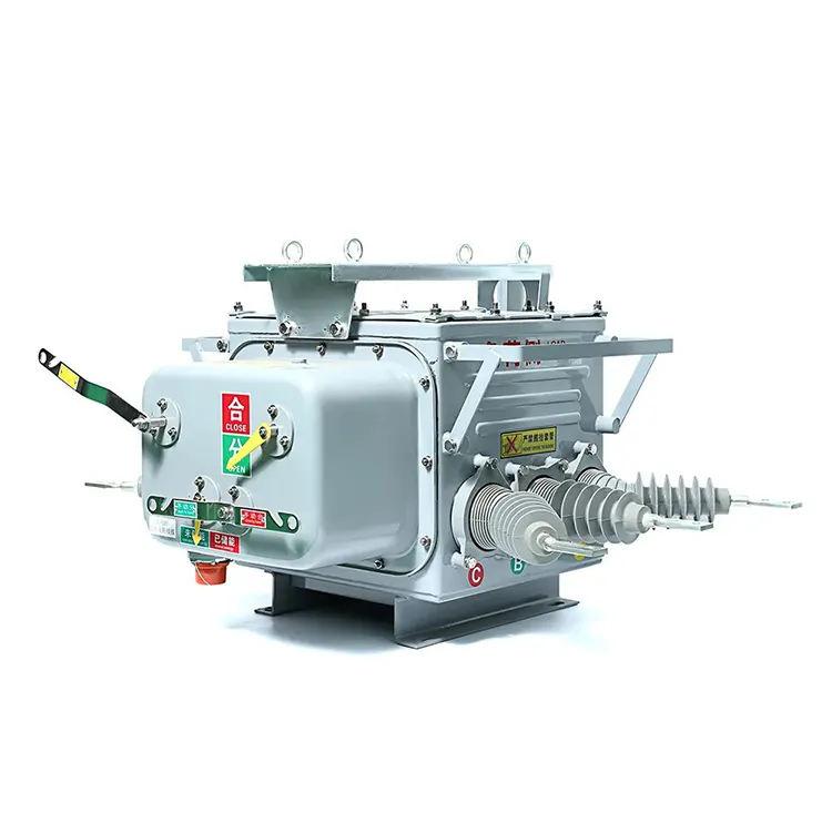
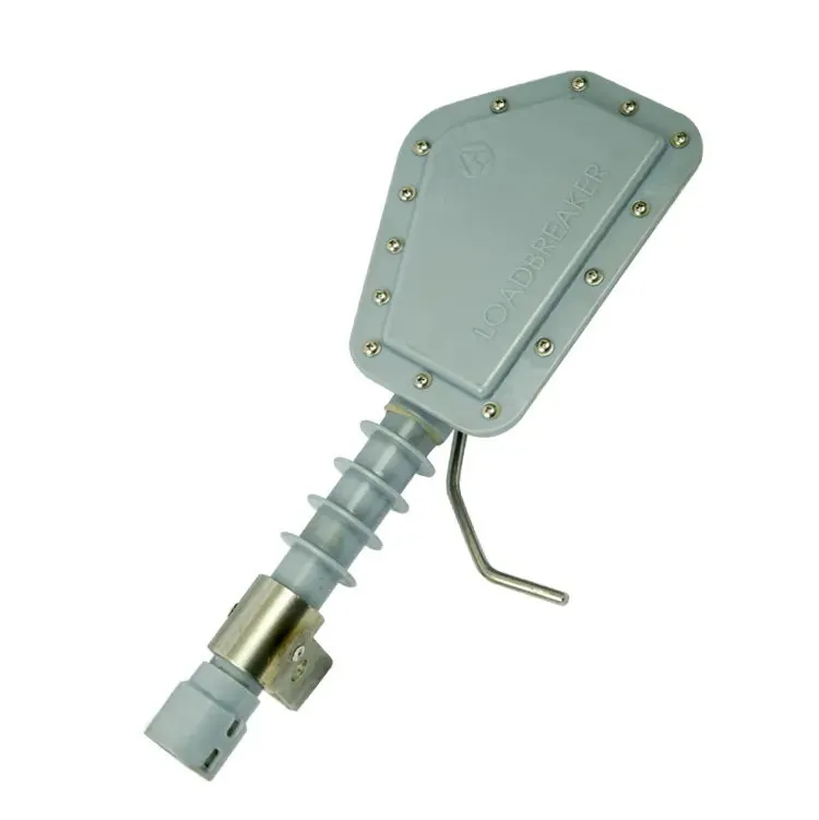


A substation equipment list can look complete while leaving important interfaces undefined. A breaker may be specified without confirming its trip supply, an instrument transformer without the required measurement duty, or a busbar arrangement without a clear isolation plan. These gaps are easy to miss when each item is reviewed as a separate purchase. The useful way to understand substation components is to follow their functions and the connections between them. Which part transfers power, which measures the system, which decides that a fault requires a trip, and which actually interrupts current? Those distinctions turn a list of parts into an understandable system.
A power transformer changes voltage, busbars join circuits, and circuit breakers perform specified switching and interruption duties. Instrument transformers provide signals for measurement and protection. A CCVT is a capacitively coupled voltage transformer, so its measurement function concerns voltage rather than current; a CT serves the current-measurement role. Disconnectors provide isolation within their declared duties and are not interchangeable with fault-interrupting breakers. The station’s single-line diagram establishes the main electrical relationships, while protection, control and wiring documents define the signals and interfaces needed to make the equipment function together.
What are the main substation components?
The electrical substation overview describes switching and transformation as separate functions. Not every station needs every device listed below, and the arrangement depends on system voltage, network duty and operating requirements.
| Component | Main function | Common misunderstanding |
|---|---|---|
| Power transformer | Transfers power between voltage levels | Assuming every switching station requires one |
| Circuit breaker | Switches and interrupts within its specified duties | Assuming the breaker alone determines protection selectivity |
| Busbar | Provides a common electrical connection for circuits | Treating its layout as only a mechanical detail |
| CT | Provides current-related signals for measurement or protection | Choosing by ratio alone |
| VT or CCVT | Provides voltage-related signals | Confusing it with current measurement |
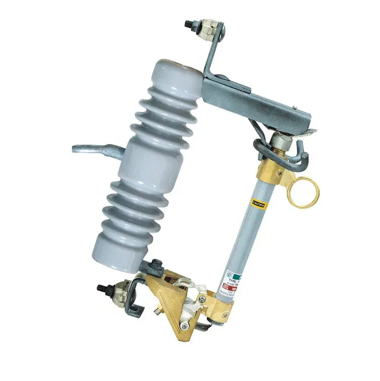
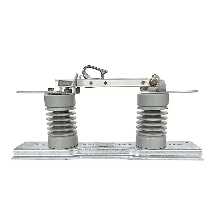
| Disconnector | Provides an isolation function within declared duties | Using it as a general-purpose fault-interrupting device |
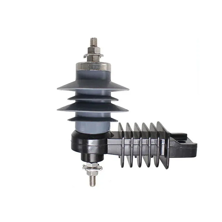
A substation components review should identify the duty of each device before comparing models. Surge arresters, auxiliary power, grounding and control equipment also belong in the complete design even though they do not all appear in a simplified power-flow sketch.
What does a circuit breaker do that a disconnector cannot?
A breaker intended for fault interruption must have the required interrupting capability for its application. 29 CFR 1910.303 addresses sufficient interrupting rating in US workplace installations. It is a regulatory requirement in that context, not evidence that a particular model meets a project’s duty.
A disconnector has a different isolation role. Certain devices have specific switching capabilities, but those must be explicitly documented; the word ‘switch’ does not establish them. The guide to disconnectors and circuit isolation explains this boundary.
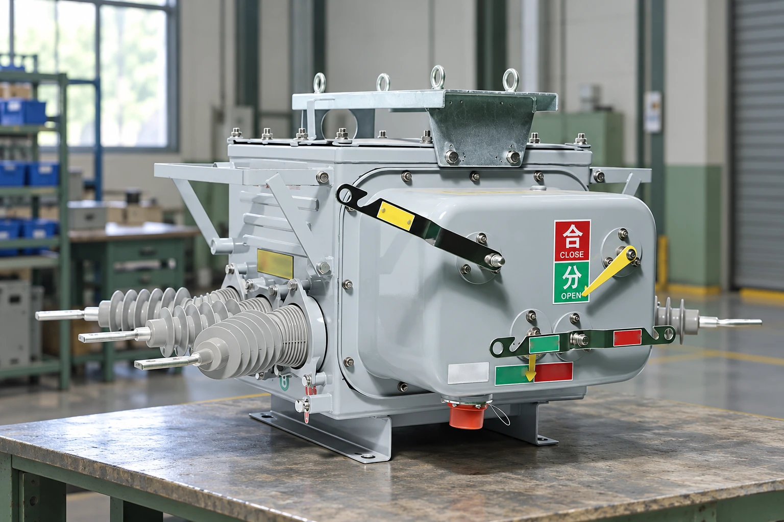
The illustrated vacuum circuit breaker is an example of medium-voltage equipment. The picture does not expose its internal interrupter or prove any breaking capacity. A purchase specification should identify the actual model and relevant test evidence, and confirm its interfaces with the protection and control system.
What does a CCVT measure?
A CCVT provides a voltage-related output using a capacitive divider and an electromagnetic stage. It is associated with voltage measurement and protection inputs, and some arrangements also support power-line carrier coupling. The voltage transformer reference explains the capacitive form. This is not a current transformer and is not required in every substation.
A suitable enquiry identifies ratio, required measurement or protection duty, burden and the associated system requirements. Carrier-coupling requirements, where present, must be stated rather than assumed from the abbreviation. The corresponding current transformer selection checklist addresses the separate current-measurement function.
Instrument-transformer signals are only part of protection. Relay settings, logic, trip circuits, breaker capability and auxiliary supply must be coordinated. A correct measurement ratio does not make the whole protection chain correct.
Why do busbar and transformer arrangements affect operation?
Busbars establish common connection points. Their arrangement influences which circuits can remain connected during a fault, maintenance or switching operation. A single bus and a more complex bus arrangement have different operating implications; neither should be selected from appearance or equipment count alone.
A power transformer also needs its connections, impedance and operating duty defined within the system study. Its power rating is important but does not independently determine downstream fault duty or protection settings. These relationships are why component selection follows an agreed single-line diagram.
Which drawings prevent component-interface mistakes?
| Document | What it establishes | Cross-check |
|---|---|---|
| Single-line diagram | Main circuits and equipment relationships | Equipment schedule and operating arrangement |
| General arrangement | Physical placement and access | Actual equipment envelopes and civil interfaces |
| Protection and control schematics | Measurement, logic and trip relationships | Approved settings and device capabilities |
| Wiring and terminal schedules | Detailed conductor and terminal connections | Device drawings and field installation |
| Equipment datasheets | Model-specific ratings and interfaces | System requirements and purchased configuration |
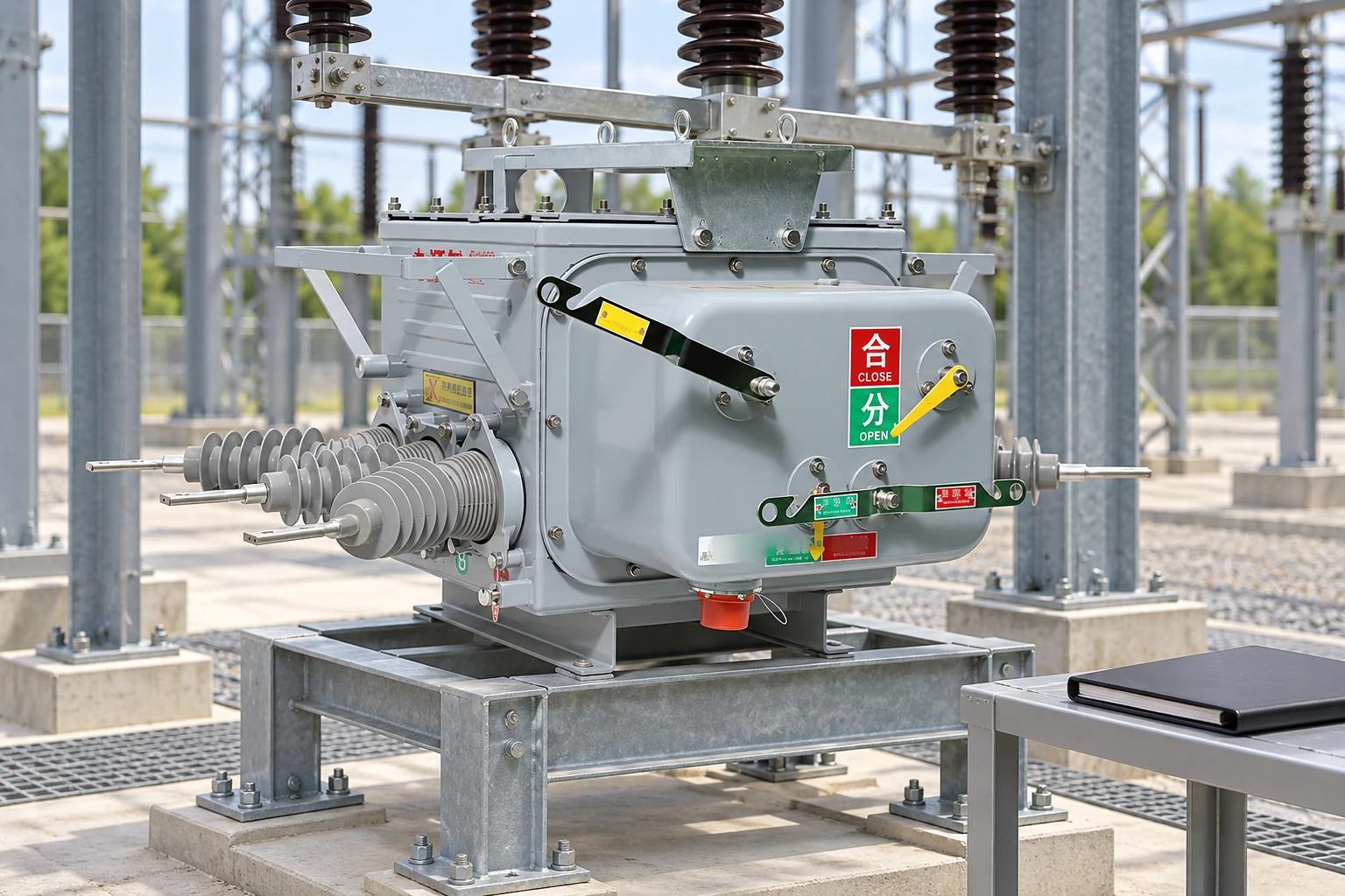
Use one agreed document revision for the enquiry and record changes explicitly. The equipment document revision guide explains why an apparently minor drawing change can affect a quotation or interface. A component that matches an obsolete drawing can still be wrong for the installed system.
Before ordering, resolve the measurement inputs, auxiliary supplies, terminal interfaces and required evidence for each item. Product standards and utility requirements must be identified by the responsible engineer; a general component article cannot establish model-specific compliance.
Frequently asked questions
What are the main components of a substation?
Typical components include power transformers where voltage transformation is needed, circuit breakers, busbars, disconnectors, instrument transformers, protection and control systems, and auxiliary equipment. The station’s function determines the actual list.
What is the role of the power transformer?
It transfers electrical power between voltage levels. Its rating, connections and other characteristics must fit the network studies and intended operating duty.
What does a substation circuit breaker do?
It performs switching and interrupts current within its specified capability. Protection equipment provides the relevant trip command, so breaker selection and protection design must be coordinated.
Why are busbars used in substations?
Busbars provide common electrical connection points for multiple circuits. Their arrangement affects operating flexibility, maintenance and the consequences of faults or equipment outages.
What does a CCVT measure?
A CCVT provides a voltage-related measurement output using a capacitive divider and electromagnetic stage. It does not measure current, and any carrier-coupling function must be specified for the actual arrangement.
How do instrument transformers support protection?
They provide current or voltage signals suitable for connected measurement and protection equipment. Ratio, burden, required duty and the full protection interface must be considered together.
How are disconnectors different from circuit breakers?
Disconnectors provide isolation within declared duties; circuit breakers perform specified switching and interruption duties. Do not assume a disconnector can interrupt load or fault current unless its documented capability explicitly permits that operation.
Which drawings show the connections between substation components?
The single-line diagram shows the main circuit relationships. Protection schematics, wiring diagrams, terminal schedules and general arrangement drawings provide the additional detail needed for signals and physical interfaces.
References
Sources checked on 2 November 2026.
- Wikipedia — Electrical substation: functions and design
- Wikipedia — Voltage transformer: capacitive voltage transformers
- 29 CFR 1910.303 — Electrical installation requirements (Cornell LII)
Summary
The essential distinction between substation parts is their function in the complete system. A transformer transfers power, a busbar connects circuits, an instrument transformer supplies measurements and a breaker performs the required interruption. Protection and control make those functions work together, while disconnectors serve a separate isolation purpose. Start with the single-line diagram, then reconcile ratings, measurement duties, auxiliary supplies and terminal details across the supporting documents. Do not accept a component simply because its main rating matches the equipment list. Fuerte’s medium-voltage vacuum circuit breakers can be evaluated within that process when their model-specific duties and interfaces match the project’s requirements.