








When a utility switching engineer prepares an outage plan, the drawing may call a device an isolator while the purchase list says disconnector. The two words are often treated as synonyms, yet the switching duty, visible isolation requirement and interlock logic can be different. Operating an off-load device against load current can damage contacts and create an unsafe state; specifying a load-break device where only isolation is required can add cost and maintenance. This guide explains the distinction, the limits of each device and the checks that should be completed before procurement.
Summary: A disconnector (often called an electrical isolator) establishes an isolation gap and is normally operated after current has been interrupted by a circuit breaker or load-break switch. A switch-disconnector or load-break switch is designed for a stated load current, but its short-circuit interruption capability must be verified separately. IEC 62271 terminology and the buyer’s protection study should control the specification. Confirm rated voltage, continuous current, making and breaking duty, interlocks and the required visible isolation before choosing a disconnector switch.
What is the difference between a disconnector and an electrical isolator?
In medium-voltage practice, a disconnector is a mechanical switching device that provides a safe isolation distance when open. “Electrical isolator” and “isolating switch” are common field terms for the same functional idea. The device is not generally intended to make or break fault current and is usually not operated while a significant load current flows. A position indicator, padlock provision and a clear open gap help maintenance personnel prove that a circuit is separated.
The word “isolator” can be used loosely in catalogues, so the name alone is not enough. The data sheet should state whether the device is a disconnector, a switch-disconnector, or a load-break switch under the applicable IEC 62271 part. A disconnector may carry normal current while closed, but its opening operation is an isolation action after upstream or downstream interruption. The isolation function should also be coordinated with earthing switches and trapped-key or electrical interlocks.
Can a switch disconnector interrupt load current?
A switch-disconnector combines switching and isolation functions. If it is classified and tested for a specified service current, it can interrupt that load current under the duty stated by the manufacturer. A separate short-circuit rating, such as a making current or short-time withstand current, still applies. It should never be assumed that a switch-disconnector can clear a fault merely because it can open a feeder during normal operation.
By contrast, an off-load isolating switch is selected for isolation and withstand rather than routine load interruption. The operating procedure normally opens the circuit breaker first, proves zero load current, then opens the isolator. A load-break switch can be used for sectionalizing where its rated current, fault-making capability and duty-cycle class match the network. The equipment schedule should make those roles explicit.
Why must load current be interrupted before an off-load disconnector opens?
Opening contacts under load creates an arc. A device designed only for isolation may not have the arc-control, contact travel or interruption medium needed to extinguish it. The resulting thermal and dielectric stress can damage contact surfaces, create an internal fault or expose an operator to an arc-flash event. The risk is increased when transformers, motors or capacitor banks are connected because inrush and reactive current can differ from the steady-state value.
Safe switching therefore follows a sequence: identify the feeder, open the circuit breaker or approved load-break device, verify indication and absence of voltage according to the site procedure, open the disconnector, then apply earths and locks where required. Interlocks should block an unsafe sequence, but operators still need an approved switching schedule. The related isolating-switch installation and maintenance guidance is useful when translating the sequence into field checks.
Which interlocks prevent unsafe disconnector or isolator operation?
Mechanical interlocks can prevent an earth switch from closing while the main path is energized, or prevent a disconnector from opening until a breaker is open. Electrical interlocks use auxiliary contacts, key exchange units or control logic to provide the same permissive signal across a lineup. The exact arrangement depends on the single-line diagram and whether the device is fixed, withdrawable, indoor or outdoor.
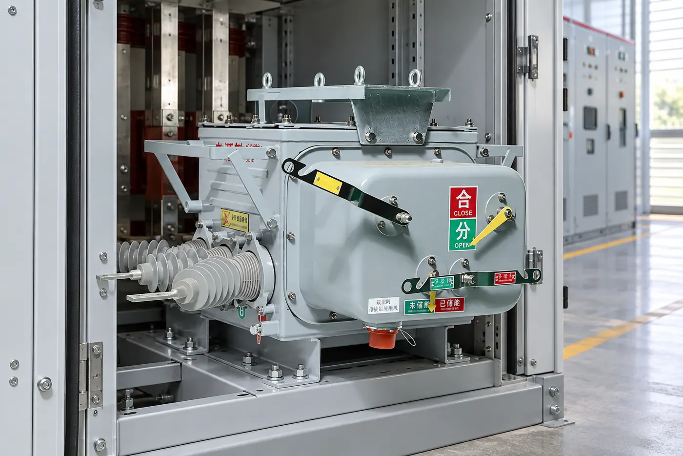
Specify the normal and test positions, trapped-key sequence, padlock points and position contacts. A position indicator should reflect the actual contact position rather than only the handle position. During commissioning, check each interlock with the equipment in the relevant electrical state and record the result. A disconnector versus isolating-switch comparison can help align terminology between the design office and site team.
Disconnector, isolator and load-break switch: what should buyers compare?
| Decision dimension | Off-load disconnector / isolator | Switch-disconnector / load-break switch | What to verify |
|---|---|---|---|
| Primary purpose | Isolation and visible separation | Routine switching plus isolation | Required switching sequence and network role |
| Load interruption | Normally excluded | Permitted only at the stated rated current | Rated operating current and duty class |
| Fault interruption | Not a circuit-breaker function | Usually requires upstream protection unless specifically rated | Short-circuit making, withstand and interruption data |
| Isolation evidence | Isolation gap and position indication | Isolation function must be declared and tested | IEC 62271 isolation requirements, indicators and locks |
| Typical applications | Maintenance isolation, busbar or line section separation | Feeder sectionalizing, transformer or ring-main switching | Load profile, earthing and interlock scheme |
| Maintenance exposure | Contact alignment, insulators and linkage | Those checks plus interruption mechanism and wear | Inspection interval and spare parts |
Which device fits common medium-voltage applications?
| Application condition | Likely device family | Procurement question |
|---|---|---|
| Dead-circuit maintenance boundary | Disconnector or isolating switch | How will absence of voltage and visible isolation be proved? |
| Ring feeder sectionalizing under normal load | Load-break switch or switch-disconnector | What current and operating sequence must it interrupt? |
| Fault clearing on a protected feeder | Vacuum circuit breaker with isolating arrangement | What protection curve and short-circuit duty apply? |
| Outdoor overhead-line branch | Outdoor isolating switch or approved load-break unit | Are pollution, wind, ice and earthing conditions covered? |
What standards and compliance points apply?
IEC 62271 is the principal family for high-voltage switchgear and controlgear; the applicable part depends on whether the product is a disconnector, switch-disconnector, circuit breaker or assembly. The IEC Webstore should be used to confirm the current edition and exact scope. IEEE C37 documents may govern an installation when the buyer’s specification follows North American practice. These documents define ratings, type tests, dielectric performance, temperature rise, mechanical endurance and switching duties; they do not make every product universally suitable.
A standard test method is different from a blanket certification. The tender should identify destination-market rules, rated lightning impulse withstand, power-frequency withstand, pollution level, altitude and short-circuit conditions. Unsupported claims about fault interruption or isolation can create re-testing, redesign, delayed energization and liability. Keep the approved drawings, routine-test reports and interlock records with the equipment file.
How should a buyer select a disconnector or switch-disconnector?
- Start with the single-line diagram and state whether the device must interrupt load current, provide isolation, or both.
- List rated voltage, continuous current, short-time withstand, peak making current and the relevant switching duty; do not infer one rating from another.
- Define mechanical and electrical interlocks, earthing-switch coordination, indication, padlocking and remote-control interfaces.
- Check installation conditions such as indoor or outdoor service, altitude, pollution, wind, ice, temperature and available maintenance access.
- Require drawings, routine-test evidence and a commissioning checklist that mirrors the approved switching procedure.
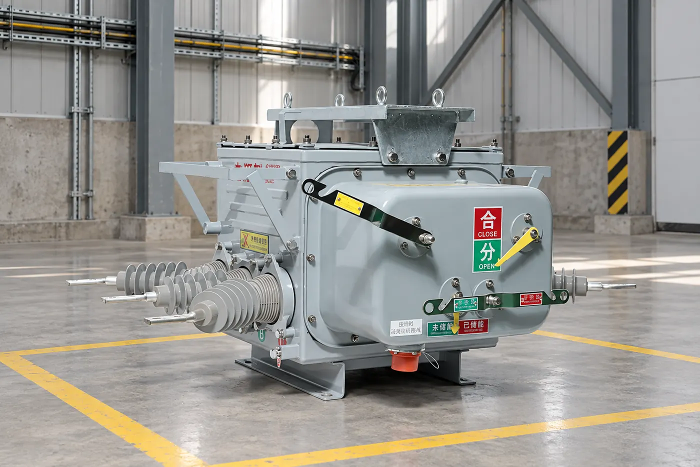
Fuerte supplies medium-voltage isolating switches and related distribution equipment for utility and EPC specifications. Its other-products directory can be used to identify the relevant equipment family, while the final configuration should follow the buyer’s ratings and interlock schedule.
Frequently asked questions
What is the difference between a load switch and a disconnector?
A load switch is designed to make and break a stated normal load current. A disconnector primarily provides an isolation gap and is normally operated after load current has been interrupted. Verify the product classification and ratings in the applicable IEC 62271 data sheet.
What is the difference between an on-load isolator and an off-load isolator?
An on-load device is rated for a specified switching current and may be operated while that current flows. An off-load isolator is intended for isolation after a breaker or load-break switch has opened. The operating sequence and interlocks must match the manufacturer’s instructions.
What is the difference between a disconnector and an isolator?
In many medium-voltage documents, the terms describe the same isolation function. Regional terminology can differ, so the tender should identify the IEC product category, isolation requirement and switching duty rather than rely on the name alone.
Is a load-break switch an isolator?
It can provide an isolation function if it is designed and tested as a switch-disconnector. That does not make every load-break switch a fault-current interrupter. Check isolation, load-switching and short-circuit ratings independently.
Which switching device cannot interrupt fault current?
A basic disconnector or off-load isolator is not intended to interrupt fault current. Fault clearing is normally assigned to a circuit breaker or an approved current-limiting device coordinated with protection settings.
How much current can a load-break switch interrupt?
Only the rated operating current stated for that particular device and duty. It may be lower than the short-circuit withstand or making-current rating. Use the tested nameplate values and network study rather than a generic load-break label.
References
- IEC Webstore, IEC 62271 high-voltage switchgear and controlgear standards.
- International Electrotechnical Commission, terminology and conformity resources.
- IEEE Standards, IEEE C37 switchgear standards where specified by the buyer.
- CIGRE, technical guidance on high-voltage switchgear operation and maintenance.
The practical rule is simple: interrupt current with the device rated to interrupt it, then isolate and earth with a device designed to prove a safe boundary. Confirm the ratings, sequence and interlocks before the purchase order is released. For a project-specific isolating-switch configuration, contact Fuerte with the single-line diagram and required standards.