








On an overhead distribution feeder, a line arrester is installed along the line itself rather than only at a station or a transformer. Utilities use this approach where exposed spans, equipment points, or repeated surge damage justify protection between stations. The purchasing difficulty is that placement, spacing, and coordination cannot be read from a product page.
This guide organizes the placement and coordination questions for distribution feeders and shows what an RFQ should record. It does not state spacing figures, predict outage performance, or extend any conclusion to transmission lines. For a related technical topic, see Surge Arrester Grounding: What an RFQ Should State About the System.
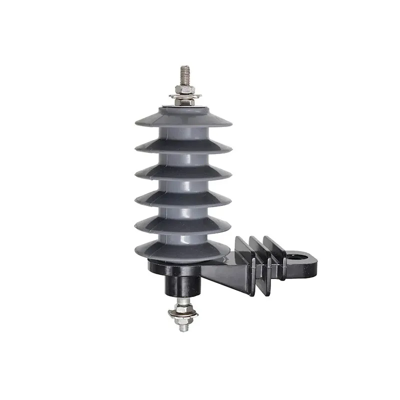
What a line arrester does on a distribution feeder?
Along a feeder, an arrester limits surge voltage at the position where it is connected, which is why position matters as much as the device. Equipment points such as cable transitions, switches, and reclosers concentrate value and vulnerability, while long exposed spans collect lightning activity. Each candidate position has its own justification.
Distribution feeders differ from transmission lines in structure height, insulation levels, earthing arrangements, and maintenance practice. Conclusions written for transmission projects therefore do not transfer directly, and this guide stays with distribution.
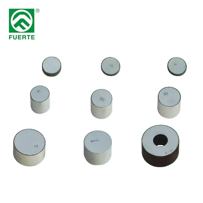
For family-level orientation, the FUERTE lightning arrester range shows the product scope. Wider grid context sits in the published overview of lightning and surge arresters for industrial power grids, which this page does not repeat.
How should buyers exposure review before any placement talk?
Placement discussions go wrong when they start from a device count instead of an exposure picture. Useful exposure information includes feeder routing, terrain and tree shielding, documented lightning activity, historical damage or interruption records, and the location of equipment the owner most wants to protect.
Record where the feeder crosses open ground, ridgelines, or water, since shielding changes along the route. Sections rebuilt with new equipment may deserve a different review than old sections with a stable history.
| Exposure input | What to record | Source |
|---|---|---|
| Route context | Open spans, shielded spans, elevation changes | Route maps and inspection notes |
| Event history | Surge damage, interruptions, replaced equipment | Owner maintenance records |
| Equipment points | Cable ends, switches, reclosers, transformer positions | Feeder one-line diagram |
| Lightning context | Documented activity data the owner accepts | Owner-designated data source |
An RFQ that attaches this picture lets a supplier respond to the actual feeder instead of a generic assumption.
How should buyers placement and spacing logic without fixed numbers?
Placement logic on distribution feeders usually follows three moves: protect named equipment points, cover the most exposed sections identified in Part 2, and keep the arrangement consistent so crews can predict what sits on each structure. The order of positions comes from the owner’s review, not from a catalog.
Spacing is the question buyers most want answered with one number, and it is exactly the value this page does not supply. Interval choices depend on insulation levels, earthing behavior, exposure, and the study method the network operator applies. The RFQ should state who produces the placement study and which basis it uses.
A workable RFQ sentence reads: “Positions and intervals follow the owner’s placement study; the supplier quotes the devices, fittings, and documentation for the listed positions.” That keeps design responsibility with the owner and quotation responsibility with the supplier.
How should buyers coordination with insulators and earthing at the structure?
At each structure, the arrester works inside an existing arrangement of insulators, hardware, and earthing. The study compares insulation withstand with the arrester’s protective characteristics and checks how the earth connection behaves during surge events. Those comparisons belong to the owner’s engineering, and the RFQ records their outputs.
Two practical interfaces still belong in procurement documents. First, the connection arrangement: line lead, earth lead, and any disconnector or external gap the owner’s practice requires should appear on the installation drawing. Second, the earthing interface: which earth conductor the arrester uses and how it reaches the structure earth.
Where a feeder position protects a transformer point, the interface questions in the published guide on transformer surge arrester coordination apply to that equipment, and station positions follow the separate substation protection scope review. This page keeps its scope on the line sections between those points.
How should buyers maintenance access and monitoring in the placement plan?
A position that cannot be inspected tends to disappear from maintenance programs. Placement reviews therefore weigh access: working position on the structure, reachability by available equipment, patrol frequency on that section, and visibility of any failure indication.
Monitoring choices belong in the same discussion. Some operators specify disconnectors with visible indication, others use counters or periodic inspection only; the owner’s practice decides. The RFQ should state which monitoring arrangement applies so quotations include the right accessories.
Keep replacement logistics visible as well. A consistent arrangement across the feeder shortens crew time and reduces the chance of an incorrect reconnection during storm restoration work.
What a placement plan does not establish?
A placement plan does not establish an outage guarantee, a compliance status, or the adequacy of insulation and earthing on the feeder. Those conclusions require the owner’s studies, records, and acceptance process.
The plan also does not convert transmission-line practice into distribution answers. Structure geometry, insulation coordination, and earthing conditions differ enough that each network class needs its own review basis.
Finally, a plan on paper does not verify installation quality. Lead routing, earth connections, and torque and fitting practice are field matters confirmed through the owner’s installation and inspection records.
How should buyers rFQ inputs and product context for distribution feeders?
Assemble the RFQ so that every supplier sees the same feeder facts and the same boundaries of responsibility. State which values are confirmed and which are pending owner decisions.
| RFQ input | Content | Owner of the value |
|---|---|---|
| Feeder identification | Voltage class, feeder name, section list | Network operator |
| Exposure basis | Route, history, and data sources from Part 2 | Owner records |
| Placement plan | Study owner, method basis, listed positions | Owner engineering |
| Structure interface | Mounting, leads, disconnector or gap practice, drawings | Owner standards |
| Earthing information | Earth conductor arrangement at listed structures | Owner design documents |
| Maintenance constraints | Access, patrol practice, monitoring arrangement | Operations team |
| Commercial items | Quantities by position, documentation requests, delivery scope | RFQ issuer |
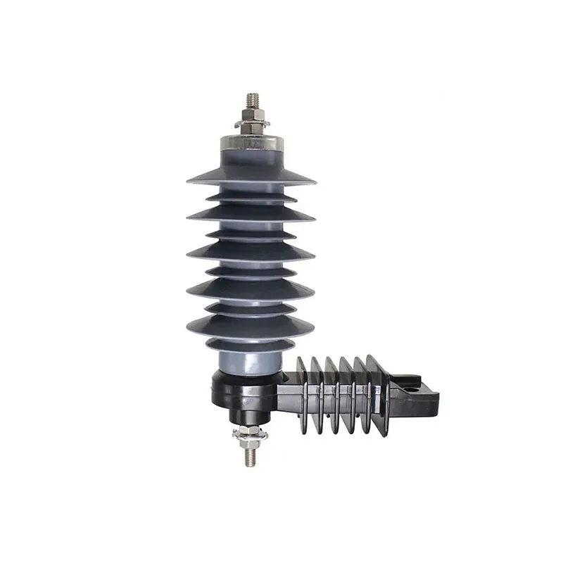
For product context on distribution feeders, the YH5(10)W-10 surge arrester product context page presents a polymer ZnO design for overhead distribution use. It is not a universal recommendation, and this article states no SKU ratings; request the exact SKU documentation and review it against the listed positions.
To start a quotation discussion for listed feeder positions, contact FUERTE with the RFQ set. A useful reply names its assumptions, the documents reviewed, and the items still waiting on owner confirmation.
A useful 2026 review adds one evidence checkpoint that many legacy articles omit: the standard edition and the voltage terminology must be recorded together. IEC 60099-4 is the relevant reference for metal-oxide arresters on AC circuits above 1 kV, while MCOV, rated voltage, temporary overvoltage exposure, residual voltage and energy duty answer different questions. A catalogue number therefore cannot replace the owner’s insulation-coordination basis. Record the source document, revision date and the system earthing assumption beside every value in the RFQ.
The same discipline applies to physical installation. Lead length, earth routing, equipment separation and the actual protected terminal can change the engineering review even when two offers carry the same nominal voltage label. Current search results repeatedly surface MCOV, TOV, residual-voltage and energy questions, but those are prompts for verification, not universal setpoints. Buyers should ask suppliers to identify the test report, declared standard edition, drawing revision and unresolved project input rather than turning a general guide into a guaranteed protection claim.
FAQ
Where are line arresters installed on overhead distribution feeders?
Typical review positions are documented equipment points such as cable transitions, switches, and reclosers, plus the exposed sections identified in the owner’s exposure review. Actual positions come from the owner’s placement study.
How far apart should line arresters be placed?
No universal interval exists. Spacing depends on insulation levels, earthing behavior, exposure, and the study method the network operator uses, so the RFQ records the study basis instead of a copied number.
Do line arresters replace insulator or earthing improvements?
No. Arresters work inside the existing insulation and earthing arrangement, and the owner’s study decides how the three interact. A placement plan is not a substitute for insulation or earthing engineering.
What exposure information supports a placement review?
Route context, shielding, documented lightning activity, damage and interruption history, and the location of valuable equipment points. Attach these records to the RFQ so suppliers respond to the actual feeder.
How does maintenance access affect placement choices?
Positions need a workable inspection and replacement path: reachable working positions, patrol visibility, and the monitoring arrangement the operator specifies. Poorly accessible positions tend to be dropped from maintenance programs.
What should an RFQ state for distribution line arresters?
Feeder identification, exposure basis, placement study ownership, structure and earthing interfaces, maintenance constraints, quantities by position, and the documentation requested for the exact offered SKU.
Does this guide apply to transmission line arresters?
No. Transmission projects involve different structures, insulation coordination, and earthing conditions, so their placement practice needs its own review basis outside this page.
What should a 2026 surge-arrester RFQ record first?
Start with the protected interface, system voltage and earthing arrangement, continuous-voltage requirement, temporary-overvoltage exposure, installation drawing and requested standard edition. Ask the supplier to identify each source document and every unresolved project input. A nominal voltage label alone cannot establish the correct device or a protection outcome.
Does MCOV by itself select a metal-oxide arrester?
No. MCOV describes the maximum continuous power-frequency operating voltage in the relevant terminology, but selection also depends on system earthing, temporary overvoltage, insulation coordination, discharge duty, residual-voltage evidence and installation geometry. The owner or EPC study should control the final values; the article provides a review path rather than a universal rating table.
Why should lead routing appear in the arrester review?
The arrester protects at its connection point, so the conductor and earth paths form part of the physical protection arrangement. Length, bends, separation and routing can change the voltage seen at the protected terminal. Record the proposed layout and ask for a drawing-based review instead of assuming that two devices with the same catalogue voltage have identical installed behavior.
References
- IEC 60099-4, Metal-oxide surge arresters for AC power circuits above 1 kVOfficial IEC scope and test-standard reference; accessed 2026-10-08.
- NEMA surge arrester standardsStandards-navigation reference for arrester terminology and application; accessed 2026-10-08.
- PSCAD metal-oxide surge arrester referenceDefines MCOV in modelling context; project values remain to be confirmed.
- Surge arrester selection: MCOV, voltage and energyCurrent SERP topic signal for buyer questions; numeric claims require project evidence.