








A medium-voltage breaker can match the required voltage class yet still be unsuitable for an existing panel. Control voltage, terminal geometry, auxiliary contacts, racking positions and interlocks determine whether the installed breaker and protection system can perform the intended sequence. These interfaces need approval before installation begins; discovering a mismatch during commissioning can delay energization and require wiring or mechanical work. This guide follows the installation from drawing review through mounting, connections, functional checks and handover. It distinguishes general planning checks from the model-specific procedures and acceptance limits that must come from the equipment manufacturer and the responsible project engineer.
Summary: Treat a vacuum circuit breaker (VCB) installation as an evidence-controlled handover, not a mounting task. Verify nameplate data, transport condition, mechanical travel, control voltage, interlocks, earthing, and relay logic before applying primary voltage. IEC 62271-100 addresses AC circuit-breaker requirements, while IEC 62271-1 and IEC 62271-200 define common and switchgear-level interfaces. Record each test result and resolve discrepancies before commissioning.
Define the installation boundary before work starts
A qualified electrical person should establish the work boundary, isolation point, permit requirements, test instruments, and responsible sign-off before the breaker is moved. Site rules and local law determine who may perform switching, testing, and energization; the contractor should follow the project method statement and the equipment manual rather than assume one universal sequence.
Confirm the project single-line diagram, panel layout, terminal schedule, protection settings, and manufacturer data sheet are the current revisions. The selected vacuum circuit breaker selection must match the system voltage, continuous current, short-circuit duty, control supply, installation position, and interface dimensions stated in the approved design.
Pre-installation checks that prevent rework
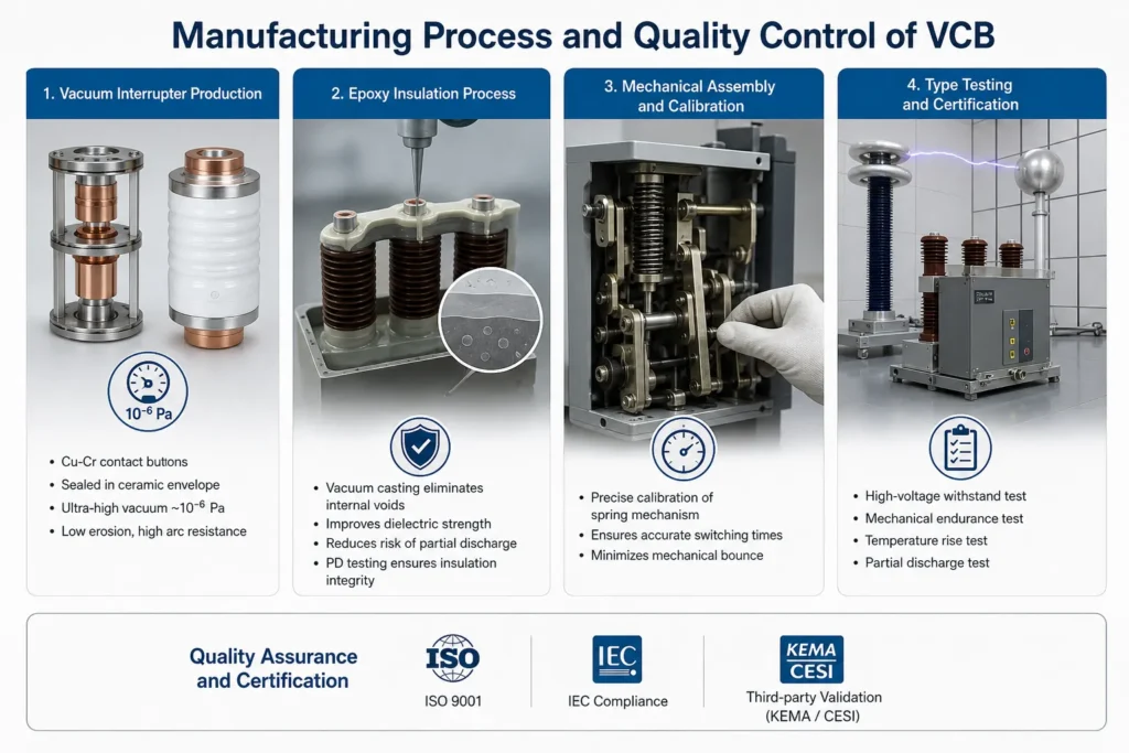
Complete a document review and a physical inspection before connecting anything. A visual check cannot replace the tests specified by the manufacturer or project; it is a gate that prevents damaged or misidentified equipment from entering the panel.
| Check point | Evidence to record | Why it matters |
|---|---|---|
| Identity and ratings | Nameplate, serial number, rated voltage/current, interrupting duty, control voltage | Prevents a rating or coil mismatch with the feeder and relay scheme |
| Transport and storage condition | Crate report, photographs, moisture/contamination observations, loose-part list | Finds damage or contamination before it becomes a commissioning fault |
| Mechanical readiness | Breaker position, racking path, shutters, interlocks, fasteners, manual operation result | Confirms the truck and primary contacts can move without binding |
| Electrical readiness | Insulation-resistance readings taken with the approved test method and limits | Provides a baseline and identifies an insulation issue before energization |
| Interface documents | Latest wiring diagram, terminal schedule, relay file, earthing arrangement | Aligns field connections with the design authority’s control logic |
Do not infer an acceptance limit from a generic table. Use the equipment manual, project specification, and applicable test procedure, and document the instrument identification and environmental conditions alongside each reading.
Mechanical installation and electrical interfaces
Mechanical fit, alignment, and torque
Clean the cubicle interfaces, confirm the breaker is supported as designed, and check that racking, shutter, and position-indication mechanisms operate through their intended travel. Align primary contacts without forcing the truck into the service position. Apply the specified torque with a calibrated tool and record the joint reference; “tight by feel” is not a repeatable installation method.
Control and protection wiring
Trace each conductor from the approved terminal schedule to the closing coil, trip coil, spring-charging motor, auxiliary contacts, anti-pumping circuit, and protection relay. Verify polarity where the circuit requires it, confirm the actual control supply under load, and prove that “breaker open,” “breaker closed,” “service,” and “test” indications agree with the physical position. Review how a vacuum circuit breaker works before changing a contact assignment or timing expectation.
Commissioning sequence and evidence pack
Commissioning should progress from document and dead checks to functional checks, then to controlled energization. The responsible engineer should define hold points; a successful close/open command alone does not prove relay coordination or primary-circuit readiness.
- Dead functional checks: Operate the breaker in the test position and verify close, trip, spring charge, anti-pumping, local/remote selection, and all interlocks.
- Signal checks: Inject or simulate the agreed control signals and confirm relay input/output indications, trip-circuit supervision, and remote status feedback.
- Protection review: Compare the approved relay file with the installed settings and confirm the trip path is compatible with the breaker coil and control supply.
- Primary-circuit checks: Complete the specified insulation, contact-resistance, phasing, and withstand or other project tests using approved methods and limits.
- Controlled energization: Energize only after the permit, barricade, interlock, and switching sequence have been reviewed and signed. Monitor indications and record the as-left state.
The handover pack should include the signed checklist, test-instrument IDs, readings, wiring mark-ups, relay settings, defect close-out, and a clear statement of what was tested and what remains outside the contractor’s scope.
Installation faults: symptoms, checks, and corrective actions
When a VCB will not close, trips unexpectedly, or shows conflicting status, isolate the symptom from the cause. Start with the simplest evidence: control voltage at the device, continuity and terminal tightness, interlock position, and the latest drawing revision. For feeder-level coordination context, see distribution protection coordination.
| Observed symptom | Likely installation cause | Diagnostic path | Corrective action |
|---|---|---|---|
| Close command does not operate | Low control voltage, open permissive, incorrect terminal, or spring not charged | Measure voltage at the coil while commanded; check permissives and spring indication | Correct the wiring or supply issue, then repeat the dead functional test |
| Breaker trips immediately | Relay output logic, trip-circuit wiring, or protection settings do not match the design | Review event record, trip path, relay file, and coil polarity where applicable | Restore the approved logic/settings and obtain design-authority sign-off |
| Position indication disagrees | Auxiliary-contact assignment, actuator adjustment, or racking position error | Compare physical position with contact continuity and panel indication | Adjust or re-terminate only against the current terminal schedule |
| High contact resistance or heating | Contaminated interface, misalignment, or joint torque outside specification | Inspect contact surfaces and repeat the specified resistance/torque checks | Clean, realign, or remake the joint as directed by the manufacturer |
| Insulation result is outside the project limit | Moisture, contamination, damaged insulation, or unsuitable test setup | Verify test connections and conditions, inspect, dry/clean if permitted, and retest | Quarantine the equipment if the result remains unacceptable and escalate |
Never defeat an interlock to “prove” a suspected fault. If the symptom persists after the documented checks, stop and involve the manufacturer or design authority with the complete evidence pack.
Standards scope and project consequences
- IEC 62271-1 sets common specifications for high-voltage switchgear and controlgear, including general service and test principles.
- IEC 62271-100 covers AC circuit-breakers, including applicable performance and type-test requirements.
- IEC 62271-200 addresses AC metal-enclosed switchgear and controlgear for rated voltages above 1 kV and up to the scope stated by the edition.
These standards define technical requirements and test frameworks; they are not, by themselves, a blanket site permit or a universal product certificate. The contract, destination-market rules, utility specifications, and edition named in the purchase documents determine what is applicable. Unsupported compliance language can create a documentation dispute, failed witness point, or delayed handover, so state exactly which tests and documents were supplied.
Procurement and handover decisions for contractors
Before placing an order, ask for the interface schedule, outline drawing, control-voltage options, terminal diagram, routine-test documentation, spare-part list, and installation/maintenance manual. Confirm the supplier can answer project-specific questions without changing the approved design. A configurable product is useful only when the final configuration is frozen, traceable, and reflected in the drawings.
For projects needing a documented configuration or replacement unit, OEM vacuum circuit breaker support can be evaluated against the same technical schedule, test evidence, and change-control requirements as any other source.
Preguntas frecuentes
Who is allowed to install and commission a vacuum circuit breaker?
The project should assign installation, testing, and switching to personnel who are qualified under the applicable law, site rules, and employer authorization. The boundary and sign-off roles should be written into the method statement; a product manual cannot replace those requirements.
What should be checked before a VCB enters the service position?
Verify identity and ratings, physical condition, mechanical travel, interlocks, earthing, control voltage, wiring, and the approved test results. Use the manufacturer and project limits for insulation, contact resistance, and any withstand test, and record the instrument and environmental conditions.
Why does a breaker close locally but not from the control room?
The remote permissive, selector switch, interposing relay, communication I/O, or auxiliary-contact feedback may be open or misassigned. Compare the remote command path with the terminal schedule and test each point while the breaker remains in the permitted test condition.
What causes nuisance tripping after installation?
Common installation causes include an incorrect relay file, a trip-circuit wiring error, an incompatible coil supply, or a status contact that creates a false permissive. Review the event record and measured control voltage before changing protection settings.
Which IEC standards should appear in the project documentation?
Identify the editions and applicable clauses of IEC 62271-1, IEC 62271-100, and, where metal-enclosed switchgear is involved, IEC 62271-200. The contract and destination-market requirements decide the final list; cite the supplied test reports rather than claiming compliance without evidence.
Conclusion
A reliable VCB installation is built at the interfaces: the approved drawing to the terminal, the truck to the cubicle, the relay output to the trip coil, and the test result to the handover record. Contractors who verify those interfaces before energization catch most rework while the equipment is still accessible. Set explicit hold points, use the manufacturer’s limits, and keep the qualified-personnel boundary visible throughout the job. When a fault appears, preserve the event record and check voltage, continuity, interlocks, and settings in that order; avoid bypasses that hide the cause. The practical takeaway is simple: install to the documented configuration, test the complete chain, and only then release the breaker for service. A supplier such as Fuerte can be brought into that decision with the same drawings, evidence, and change control expected from the project team.