

A fuse symbol can show where protection belongs without identifying the replacement fuse. The nearby reference may point to a parts list, while the current rating appears on another sheet. Older drawings can also use a different symbol convention from the equipment documentation supplied today. Reading only the small graphic therefore risks confusing a circuit function with an approved component. This guide explains how to recognize the fuse function, interpret the nearby markings and follow the drawing through to the actual device. It also covers the practical question that arises during maintenance: what to do when the installed assembly no longer matches the record.
A fuse symbol represents a protective function in the circuit, not a complete purchasing specification. A common IEC-style representation is a small rectangle with the conductor line running through it; other conventions use different fuse-element shapes. Confirm the drawing’s own legend before interpreting an unfamiliar mark. The general electronic-symbol overview describes differences between symbol conventions and standards. Next, follow the device reference to the schedule or bill of materials. The symbol alone does not establish current, voltage, AC/DC duty, breaking capacity or the correct holder. Those requirements must be resolved from the associated documents.
What does the graphic show, and what does it leave out?
The graphic identifies a fuse in an electrical path. It does not reproduce the product’s physical shape: a cartridge, a bolted fuse and a fuse link within an outdoor cutout can all be represented at a functional level. On a single-line drawing, one representation may summarize a multiphase arrangement, so the drawing convention must also establish how many actual devices are involved.
| Drawing feature | Typical purpose | What still needs checking |
|---|---|---|
| Fuse graphic | Identifies the protective function in a circuit | The particular symbol convention and component specification |
| Device reference | Connects the drawing to schedules and records | Exact matching entry and any assembly suffix |
| Current or voltage note | States one electrical requirement | Other ratings and the note’s scope |
| Cross-reference | Points to another drawing or location | Correct sheet, revision and associated circuit |
Do not assume a rectangular shape is a fuse merely because it sits in series with a conductor. Other components can use rectangular forms. The complete graphic, label and legend must agree. Where a reproduction is blurred or partially cropped, obtaining the original drawing is safer than reconstructing a symbol from its outline.
How should nearby letters and numbers be read?
A drawing might identify a fuse as F1 or use a project-specific reference scheme. That example is a designation, not a universal rule. A neighbouring number may instead identify a wire, terminal, drawing grid or electrical value. Look at the legend, title block and schedule headings before assigning meaning to it.
The fuse rating is a separate matter. A current value does not identify the full protection characteristic, and a voltage note does not establish AC/DC interchangeability. The guide to AC and DC fuse ratings explains why the circuit type and interruption duty belong in the specification even when the schematic uses the same basic fuse graphic.
How is a drawing reference matched to an outdoor cutout?
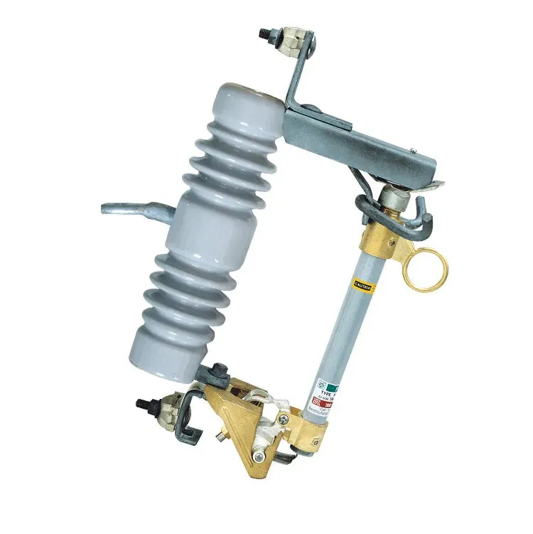
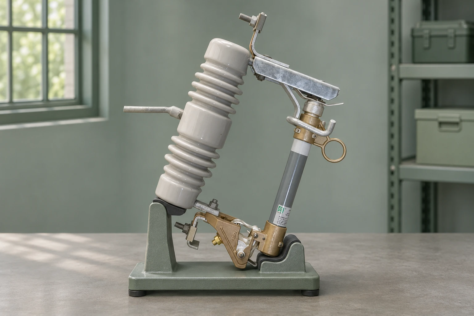
Follow the reference from the single-line diagram to the equipment schedule, then to the assembly drawing and approved fuse-link information. The cutout support, carrier and protective link are related but distinct items. An entry naming only the assembly may not identify the fitted link or show whether it is included in the supply.
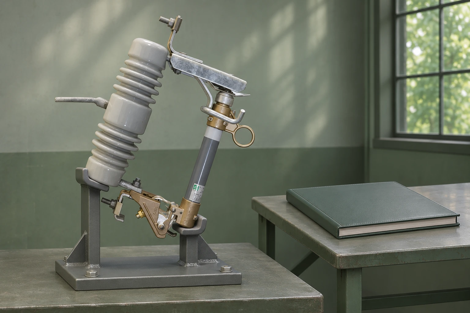
The illustration shows the physical assembly that a drawing must ultimately identify; it does not reproduce a schematic or imply a particular fuse rating. For an overhead project, the cutout drawing and supply-scope record helps keep the equipment designation, included components and document revisions together.
How is a fused switch different from a separate fuse symbol?
A schematic can show a switch function and a fuse function together, or display them as separate elements with an association defined by the legend. Read that association carefully. It may describe the functional combination without showing the physical sequence, service access or operating mechanism in enough detail for maintenance.
A combined symbol is not, on its own, proof that the equipment can interrupt a stated load or fault. Those capabilities belong to the actual device ratings and instructions. Similarly, the line drawing should not be used to infer that removal of a fuse carrier provides every required isolation function. The appropriate operating procedure must identify the actual equipment and electrical conditions.
| Question | Document that usually resolves it | Common reading error |
|---|---|---|
| Which circuit is protected? | Single-line or schematic diagram | Confusing a cross-reference with a connection |
| Which exact fuse is required? | Device schedule and approved parts list | Ordering from the symbol alone |
| Where is it physically installed? | Layout, wiring and assembly drawings | Treating schematic position as physical location |
| What operation is permitted? | Equipment instructions and site procedure | Inferring switching capability from a graphic |
Use the drawing set as a connected record. When one sheet has been revised, check whether the parts schedule and operating documentation were updated too. A technically correct schematic can still point to an obsolete part if that connection has been lost.
What should be checked when the installed equipment differs?
First verify that the correct drawing and revision are being used. Then compare the installed marking and model with the approved schedule under the site’s safe inspection procedure. Do not change an installed fuse merely to match an old drawing, or amend the drawing to match an unexplained field substitution without review.
Record the discrepancy in terms that can be resolved: reference, circuit, installed model, specified model and the relevant document revision. The responsible engineering review can then decide whether the installation or the record needs correction. A complete device reference connects the symbol to the circuit and the approved part; it does not stop at a label pasted on an enclosure.
Frequently asked questions
What does a fuse symbol look like on a circuit diagram?
A common IEC-style fuse graphic is a small rectangle with the conductor line passing through it. Other conventions use different element shapes, so confirm the complete graphic against the drawing’s legend.
Can fuse symbols differ between drawing standards?
Yes. Symbol conventions and project practices vary, and older drawings may differ from current supplier documents. Use the declared standard and drawing legend rather than treating one shape as universal.
How is a fuse identified on a wiring diagram?
Look for the fuse graphic and its device reference, then follow that reference to the circuit schedule, wiring information and parts list. A designation such as F1 is only an example of a project convention.
What information is shown beside a fuse symbol?
It may show a device reference, rating, circuit name or cross-reference. Nearby wire and terminal numbers can look similar, so check the legend and document context.
Does a diagram symbol specify the fuse current rating?
No. The graphic identifies a function. Current may appear in an adjacent note or schedule, and the full specification also needs voltage, current type, interruption duty and operating characteristic.
How is a fused switch shown in a schematic?
The drawing may combine fuse and switch functions or associate separate symbols. The legend and assembly documents define that association; the graphic alone does not prove load-switching capability.
Where should the drawing legend be checked?
Check the drawing’s legend or symbol sheet and its title-block references before interpreting an unfamiliar graphic. Confirm that the relevant sheets belong to the same approved revision set.
How can a schematic be matched to the installed fuse device?
Trace the device reference through the schedule and assembly documentation to the installed model and markings under the site’s safe inspection procedure. Investigate discrepancies rather than assuming either the drawing or the field substitution is correct.
References
Sources checked on 16 November 2026.
- Wikipedia — Electronic symbol: conventions and standards
- Wikipedia — Fuse (electrical): construction, ratings and standards
- 29 CFR 1910.303 — Electrical installation requirements (Cornell LII)
Summary
A fuse symbol is useful because it reduces equipment to its circuit function, but that simplification is also its limit. Read the legend first, separate the graphic from nearby tags and ratings, and follow the device reference into the approved schedule and parts information. Use layout and assembly drawings for physical details rather than guessing them from schematic position. If the installed device differs, resolve the document or equipment change before ordering a replacement. For outdoor distribution assemblies, Fuerte’s fuse cutout information can support the model and configuration review, while the project drawing set remains the record connecting that assembly to its circuit and selected fuse link.