


A capacitor bank may improve a power-factor figure while creating a new problem if the network’s load pattern, harmonics and switching conditions have not been assessed. The kvar total is only one input. A bank that is useful at heavy load can be excessive at light load, and the device that carries its normal current may not have the required switching duty. Procurement should therefore connect the compensation objective to the network study and the actual switching arrangement. This guide separates reactive-power selection from transient and protection questions so that the bank and its supporting equipment are specified together.
A shunt capacitor bank supplies capacitive reactive power that can offset part of an inductive load’s reactive demand. It can affect current and voltage conditions, but the outcome depends on the network and operating state. Switching introduces additional duties, and interaction with system inductance makes harmonic assessment important. A general continuous-current or short-circuit rating does not establish capacitor-switching suitability. Define the required compensation, operating stages and system conditions, then request evidence for the capacitor bank, switching device and protection arrangement in that specific application.
How does a capacitor bank affect reactive power?
The power-factor reference distinguishes real, reactive and apparent power. For sinusoidal conditions, power factor is related to the phase relationship between voltage and current. Nonlinear loads also introduce distortion, so correcting displacement alone does not necessarily resolve every power-quality issue.
A capacitor bank in a substation can reduce the reactive demand supplied from upstream under the assessed conditions. It does not create additional real energy for the load. The required amount and operating strategy should follow measured or studied conditions across the relevant demand range.
| Arrangement | How it operates | Question to assess |
|---|---|---|
| Fixed bank | Connected according to the designed fixed operating arrangement | Does compensation remain suitable at low as well as high demand? |
| Switched bank | Connected or disconnected as required by the control strategy | Which switching duties and operating frequency apply? |
| Staged compensation | Changes compensation through defined steps | Are step size, controls and interactions appropriate? |
Why do voltage and harmonics need a system study?
Reactive compensation can change the voltage profile, but the effect is not a fixed benefit independent of system strength and load. Assess the relevant operating states, including light load and planned network changes. Avoid choosing a bank solely to achieve a nominal power-factor target under one operating condition.
Capacitance interacts with system inductance. The power-factor reference notes that reactive elements can produce resonant conditions, making an engineering assessment necessary. Harmonic sources and network impedance should be reviewed before adding compensation. A reactor or filtering arrangement is a design decision supported by that assessment, not an accessory to add by guesswork.
What causes capacitor-switching transients?
When a bank is connected, charge redistributes through the available circuit impedance. The resulting transient depends on the bank, source and switching conditions. The inrush-current reference explains the initial charging behaviour of capacitors. Existing energized banks and the proposed connection arrangement can change the duty, so the supplier needs the actual system configuration.
Specify the required operating sequence and any relevant residual-charge conditions. Discharge provisions and waiting requirements must follow the equipment documentation and approved procedures. A blog calculation or visual indication is not a substitute for establishing a safe condition before work.
Which switching ratings must be checked separately?
Ask for the documented capacitive switching duties relevant to the application, along with the normal-current and fault duties. Identify whether the arrangement involves an isolated bank or switching near other energized banks, and provide the study information requested by the switching-device manufacturer.
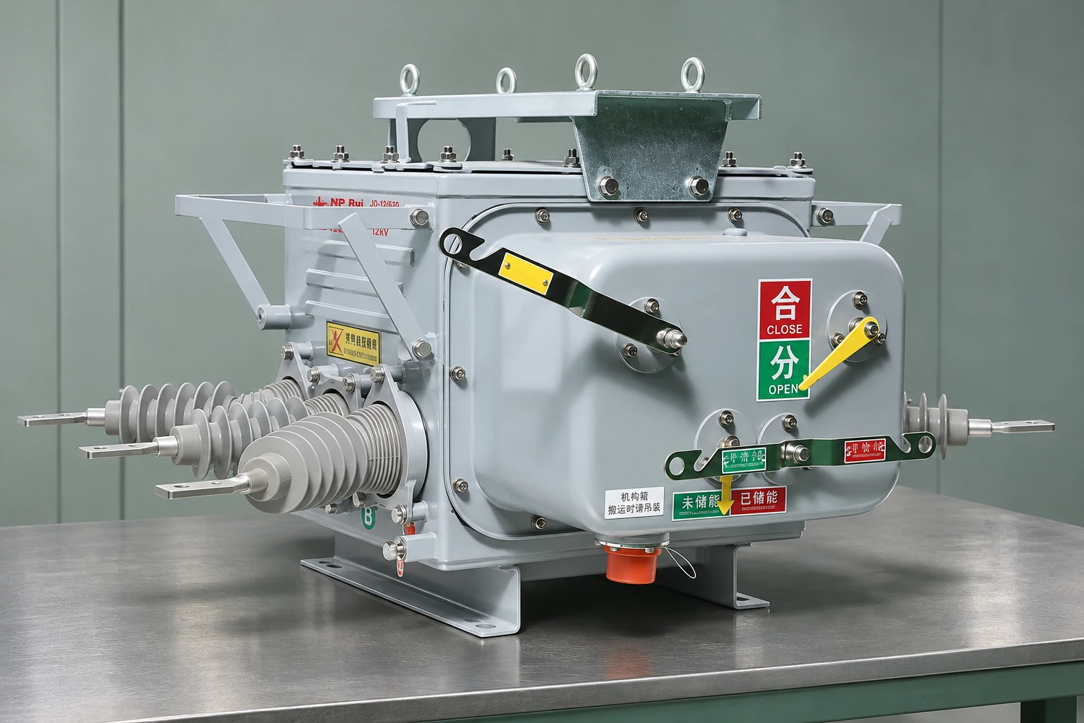
The illustrated breaker is an equipment example, not a claim that this model is approved for the proposed capacitor duty. The circuit breaker ratings review explains why a familiar voltage and current pair is only part of a specification.
29 CFR 1910.303 addresses adequate interrupting ratings in US workplace installations. That does not make a short-circuit rating evidence of every capacitive switching capability. Obtain the applicable product-standard and test evidence for the exact duty instead.
What should be sent with a capacitor-bank enquiry?
| Input | Purpose |
|---|---|
| Network voltage, frequency and relevant fault conditions | Establishes the system duty |
| Required compensation and step arrangement | Defines bank size and operating states |
| Existing banks and source impedance information | Supports transient and interaction assessment |
| Harmonic study information | Identifies relevant distortion and resonance concerns |
| Switching sequence and frequency | Defines the intended operating duty |
| Protection, control and discharge requirements | Coordinates the complete installation |
The protection measurement requirements depend on the selected scheme. Overcurrent, unbalance and other functions should be specified where the bank design and study require them, with clear measurement inputs and settings responsibilities.
Coordinate switching controls with the surrounding substation equipment. Define how the system behaves when a stage is unavailable or a control input fails. The final protection arrangement must follow the engineered design and manufacturer requirements rather than a universal checklist of relay functions.
Frequently asked questions
Why are capacitor banks installed in substations?
They can supply capacitive reactive power to support the network’s compensation objective. The required capacity and operation should follow the actual load and system conditions.
How do capacitors affect reactive power?
They can offset part of an inductive load’s reactive demand, changing the reactive power supplied from upstream. They do not provide the real energy consumed by the load.
Can a capacitor bank change the voltage profile?
Yes. The effect depends on network impedance, operating state and the amount of compensation. Study both intended operation and conditions such as light load rather than assuming voltage always improves.
What causes capacitor switching transients?
Charging and redistribution of energy during connection can produce transients. The bank, source impedance, existing energized banks and switching conditions influence the duty.
Why should harmonics be assessed before installation?
Capacitors interact with the network’s inductance and harmonic sources. An assessment is needed to identify possible resonance or unacceptable conditions before selecting compensation and any associated reactors or filters.
Which switching device ratings need to be checked?
Check the specific capacitive switching duties as well as continuous-current and fault ratings. Provide the actual bank arrangement and operating sequence, and request applicable test evidence.
What protection does a capacitor bank need?
The required scheme depends on the bank design and system study. Specify the relevant fault, unbalance and other protective functions with their measurement inputs, settings and discharge-related requirements.
How do fixed and switched capacitor banks differ?
A fixed bank follows its designed fixed connection arrangement, while a switched bank is connected or disconnected according to controls. Switched arrangements add operating duties and should be assessed across their intended states.
References
Sources checked on 9 November 2026.
- Wikipedia — Power factor: reactive compensation and system interactions
- Wikipedia — Inrush current: transformer and capacitor energization
- 29 CFR 1910.303 — Electrical installation requirements (Cornell LII)
Summary
A capacitor-bank specification should explain the compensation objective and the conditions under which the bank will operate. Establish the load and voltage requirements, assess harmonics and switching conditions, and then select the bank, switch and protection as a coordinated arrangement. Normal current, fault interruption and capacitive switching are separate duties that need the appropriate evidence. Light-load operation and existing banks should not be omitted for convenience. Keep discharge and work requirements tied to the supplied equipment’s documentation. Fuerte’s vacuum circuit breakers should only be considered after the manufacturer confirms the offered model’s suitability for the specified capacitor-switching application; this article does not establish that capability.