
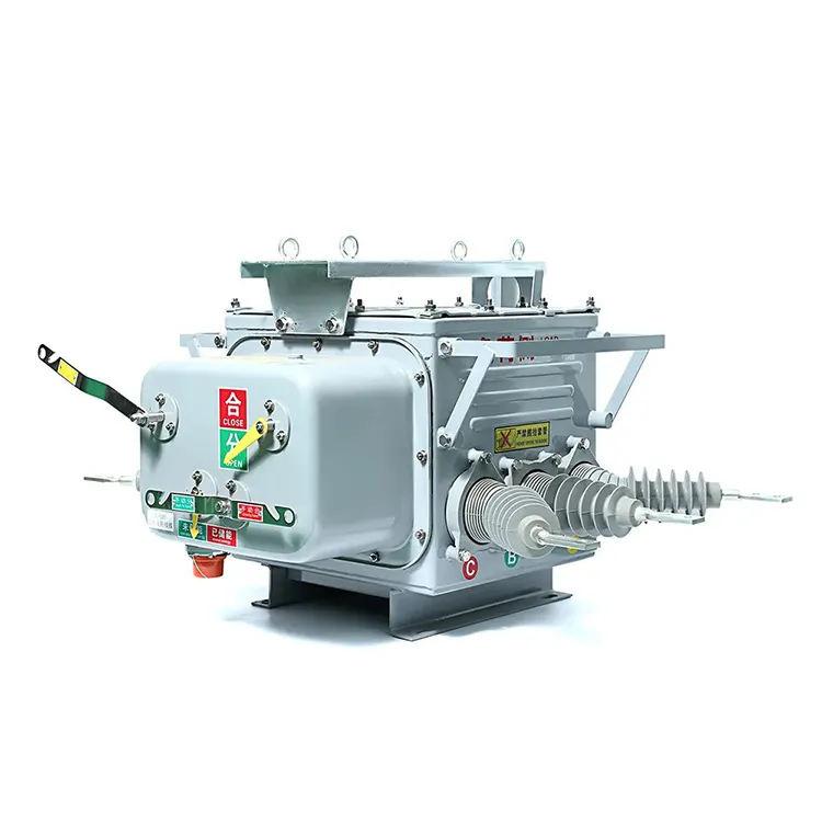
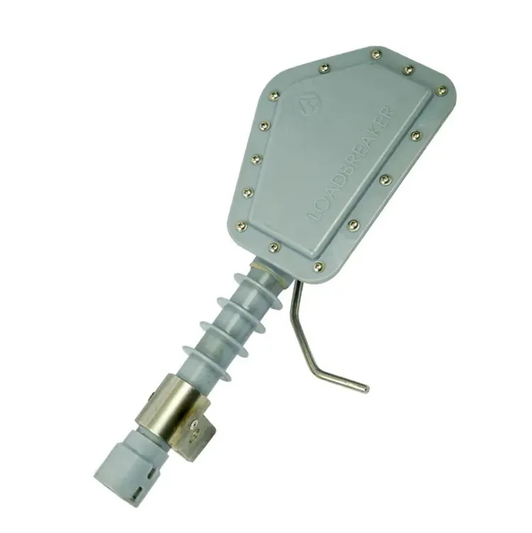


Two busbars with the same cross-sectional area can operate under different thermal and mechanical conditions. One may sit in a ventilated enclosure with documented joints and supports; another may have a different orientation, restricted cooling or connections that were never assessed as an assembly. Choosing from conductor area alone misses those differences. A useful busbar specification connects the metal section to its joints, insulation, supports and enclosure. The aim is to establish how the complete arrangement carries normal current, withstands the required fault duty and maintains the necessary separation, rather than treating a length of copper or aluminium as a finished system.
A busbar is a conductor used as a common electrical connection point for circuits. In distribution equipment it may be a rigid bar, tube or another engineered form, supported and insulated as required by the assembly. Its current capacity depends on material, geometry, connections, heat dissipation and the applicable verified arrangement. Supports must also accommodate the relevant mechanical duties. A busbar system therefore needs assembly drawings and evidence, not just a metal size. Clearance through air and creepage along an insulating surface describe different distances and must be assessed under the applicable design requirements.
How does a busbar differ from a cable?
The busbar reference describes conductors used for common connections in switchgear, distribution equipment and substations. Busbars often provide a relatively rigid arrangement with defined connection positions. Cables generally provide a flexible routing form with their own conductor and insulation construction. Neither is inherently best for every installation.
| Question | Busbar arrangement | Cable arrangement |
|---|---|---|
| How is the route established? | By the designed conductor geometry and supports | By permitted cable routing and support arrangements |
| How are connections made? | At designed joints and connection points | Through suitable terminations and connectors |
| What supports the rating? | The relevant assembled configuration and conditions | The cable type and installation conditions |
| What must be checked during a change? | Geometry, joints, supports, insulation and enclosure | Cable construction, route, terminations and installation limits |
A busbar can be bare within an appropriately designed enclosure or use an insulating system. The choice affects spacing, cooling and access requirements. A covering should not be assumed to permit any conductor spacing or eliminate the need for the assembly’s protective provisions.
Which factors affect current capacity and heating?
Conductor resistance depends on resistivity, length and area. OpenStax’s resistance explanation provides the relationship R = ρL/A. Resistive heating at a given current follows I²R, but final temperature also depends on the way the assembly releases heat.
Material, shape, orientation, ambient conditions and ventilation can therefore matter. Joints introduce additional interfaces. The conductor material comparison explains why a bulk resistivity value is useful without being a complete assembly rating.
Do not apply a universal amperes-per-square-millimetre rule as approval for an enclosed distribution assembly. Request the manufacturer’s declared conditions and the relevant verification for the proposed arrangement. If the enclosure or conductor geometry changes, review whether the original evidence still covers it.
Why do busbars need insulating supports?
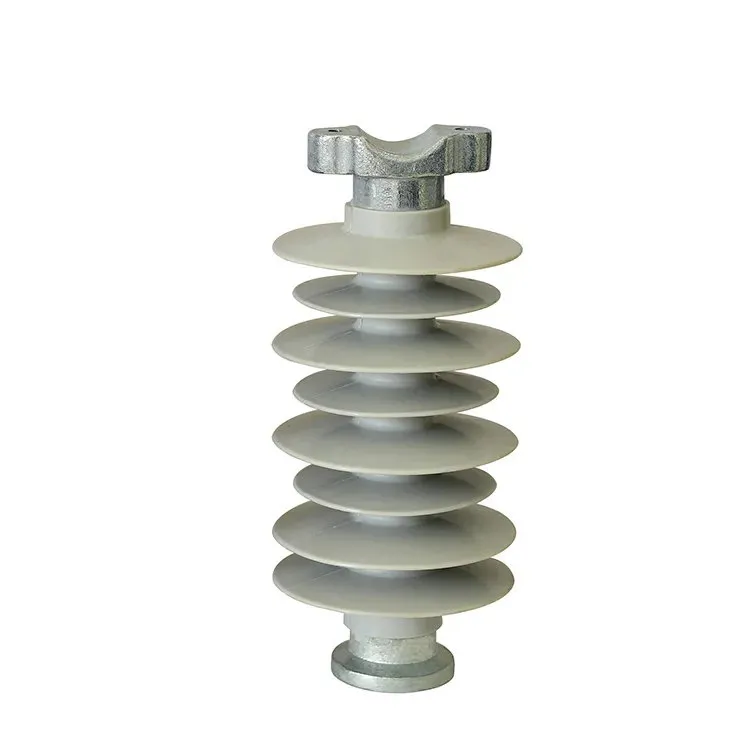
Supports hold the conductor in its designed position and maintain electrical separation. Their duties can include the conductor’s weight and the mechanical effects considered in the assembly’s fault design. A support’s material name or visual size does not establish its permitted load or electrical duty.
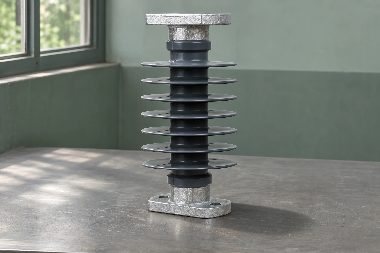
The illustrated outdoor polymer insulator shows the distinction between a visible insulating body and a fitting. It is not a claim that the model is approved for this busbar application. The guide to insulator support types explains why actual mechanical role and mounting arrangement matter when comparing components.
How do clearance and creepage differ?
Clearance is the shortest distance through air between the relevant conductive parts. Creepage is the shortest distance along the surface of insulating material between them. They describe different paths, so a long surface route does not automatically provide adequate clearance, and a wide air gap does not establish surface performance.
The required values depend on the applicable equipment design and conditions, including relevant voltage and environmental factors. Do not copy a dimension from a differently rated installation or derive it from a generic material datasheet. The approved drawing should show which distances and interfaces the designer has assessed.
Which drawings and tests should be reviewed together?
| Review item | Information needed | Reason |
|---|---|---|
| Conductor drawing | Material, dimensions, arrangement and connection positions | Identifies the actual current path |
| Joint specification | Approved surfaces, hardware and assembly instructions | Connects the design to repeatable installation |
| Support arrangement | Support type, spacing, mounting and relevant duties | Maintains the designed physical and electrical separation |
| Enclosure and cooling | Ventilation, ambient conditions and installation restrictions | Defines the thermal environment |
| Assembly verification | Applicable thermal, dielectric and short-circuit evidence | Demonstrates the duties claimed for the offered configuration |
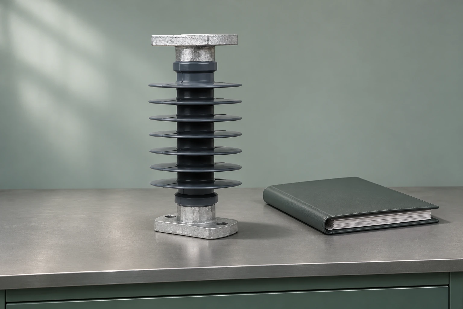
US 29 CFR 1910.303 addresses suitable electrical connections, including conductor-material compatibility. Its scope does not turn a joint into a verified busbar system, but it illustrates why material substitutions need explicit review.
Keep approved drawings and assembly instructions together. The equipment drawing revision guide is relevant when a supplier changes terminals, support positions or enclosure details. Ask which original tests and assessments remain applicable, rather than accepting an unchanged headline current rating as the whole explanation.
What should be checked after an installation change?
Review the affected interfaces and evidence. A moved support, altered joint, added connection or blocked ventilation path can change the conditions behind the assembly’s rating. The responsible manufacturer or designer should define the checks needed for that modification.
Inspection and maintenance must follow the equipment instructions and applicable work procedures. Visual appearance alone cannot establish acceptable contact resistance, temperature rise or fault withstand. Keep observed conditions separate from measured results and from conclusions that require engineering assessment.
Frequently asked questions
What is an electrical busbar?
It is a conductor used as a common electrical connection point for multiple circuits. Its form, supports, insulation and joints are designed as part of the intended equipment arrangement.
How does a busbar differ from a cable?
A busbar commonly provides a relatively rigid conductor arrangement, while cable offers a different routing and insulation construction. Selection depends on the application and installation rather than a universal preference.
Why do busbars need insulating supports?
Supports maintain the conductor’s intended position and electrical separation while carrying the specified mechanical duties. The correct support needs documented electrical, mechanical and mounting suitability.
Which factors affect busbar current capacity?
Relevant factors include material, section shape, dimensions, joints, ambient conditions, enclosure and cooling. Assess the complete verified arrangement rather than conductor area alone.
How do connections affect busbar heating?
Joints create electrical interfaces whose condition and assembly affect resistance. Follow the approved surface, hardware and tightening requirements instead of assuming the conductor’s bulk properties describe the joint.
What is the difference between phase clearance and creepage?
Clearance is a path through air; creepage follows an insulating surface. Each must meet the applicable design requirements for the actual equipment and conditions.
How does enclosure ventilation affect a busbar assembly?
Ventilation affects heat removal and therefore the temperature reached under load. Changing or obstructing it may alter the conditions behind the manufacturer’s declared rating.
What drawings and test data should be checked for a busbar system?
Review conductor and joint drawings, support details, enclosure conditions and applicable assembly-verification evidence. The documents and tests must cover the offered configuration and any relevant changes.
References
Sources checked on 9 November 2026.
- Wikipedia — Busbar: conductor forms, supports and arrangements
- OpenStax, University Physics Volume 2, §9.3 — Resistivity and Resistance
- 29 CFR 1910.303 — Electrical installation requirements (Cornell LII)
Summary
A busbar’s performance comes from the complete arrangement of conductors, joints, supports and insulation. Start with the electrical duties and installation conditions, then confirm the geometry and interfaces that the manufacturer’s evidence covers. Review thermal conditions and mechanical support alongside clearance and creepage, because no single conductor dimension answers all of those questions. Treat changes to joints, supports or ventilation as design changes requiring assessment. Keep the final drawings and instructions consistent with the installed equipment. Fuerte’s polymer insulator range provides documented product options for its intended applications; a support for a particular busbar system still requires model-specific confirmation against that assembly’s requirements.