








A maintenance team may know that it needs a trip coil or auxiliary switch and still be unable to order the right spare. The same breaker family can contain different mechanism revisions, supply voltages, connectors and mounting details. A photograph of the damaged part helps, but it rarely captures the complete identity or replacement approval. This guide names the main VCB assemblies and focuses on the service question behind the parts list: which records connect a replacement component to the exact breaker, what interfaces must remain consistent, and what verification is needed before the equipment is returned to service?
What should the buyer confirm first?
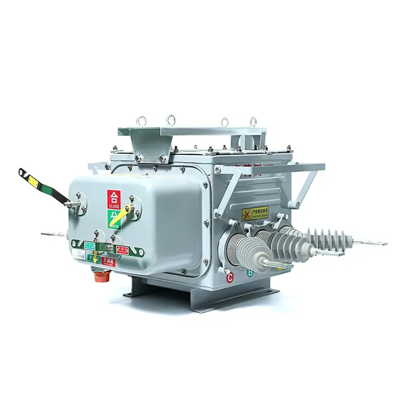
The main VCB assemblies include vacuum interrupters, conductors and terminals, insulating supports, the operating mechanism, trip/close components, auxiliaries and interlocks. Their replacement status is design-specific. Order by the complete breaker identity and the approved spare reference, not the component’s generic name or apparent size. Provide serial number, mechanism and drawing revision, control supply and photographs of identification marks. Ask the manufacturer to confirm the replacement boundary, included hardware and post-work checks. An interrupter, pole assembly and complete breaker are different supply scopes even when a quotation informally calls each of them a VCB part.
Which assembly contains the part being requested?
| Assembly | Typical items to identify | Important replacement distinction |
|---|---|---|
| Primary pole | Interrupter, conductor, terminal and associated insulation | A bottle and complete pole are different items |
| Mechanism | Actuator, linkage, latch or charging equipment | Design and revision determine compatibility |
| Control and auxiliaries | Coils, auxiliary contacts, connectors and wiring | Supply and functional arrangement must match |
| Truck or mounting | Racking parts, primary interface and earthing features | Fit includes the receiving equipment |
| Indication and interlocks | State indicators and defined mechanical/electrical restraints | Appearance does not prove the same function |
The arrangement varies between products; do not assume all listed parts exist as separate field-replaceable items. For the current path and operating sequence rather than spare identification, see the vacuum circuit breaker construction guide.
What information should accompany a spare-parts enquiry?
Start with the manufacturer, complete type designation, serial number and nameplate photographs. Add the mechanism identifier, approved assembly or wiring drawing and its revision. Where a part number is visible, copy it exactly, including suffixes; do not infer the meaning of a suffix from another model.
Describe the requested item and observed issue separately. For example, failure to trip is an observation, not proof that the coil has failed. Include the authorized inspection findings so the supplier can distinguish a component order from a request to diagnose the operating chain. The VCB nameplate checklist provides the starting identity fields.
Which interfaces can a similar-looking spare change?
A coil’s nominal voltage alone may not identify its complete duty, connector or mounting. An auxiliary switch can have a different contact schedule or actuation arrangement. A linkage or pole replacement can affect contact movement and its relationship to the mechanism. Compare the controlled spare specification rather than approving by a photograph.
For withdrawable units, the truck, primary disconnects, secondary connection and receiving-cell interlocks form part of the compatibility question. Siemens’ replacement-breaker page discusses control of mechanism-operated cell switch movement in its own engineered replacements. This illustrates why the receiving-cell function matters; it does not establish a generic cross-brand replacement rule.
When should a complete assembly replace an individual part?
Use the manufacturer’s approved service boundary. Some designs support replacement of a listed component; others require a pole or mechanism assembly with defined adjustments and checks. The decision should consider support status, tools, qualified personnel, inspection requirements and the extent of damage.
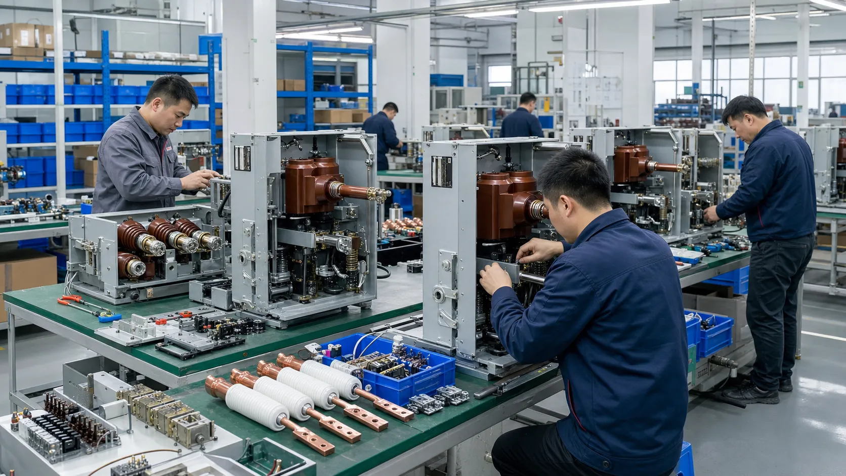
Ask what the supplied kit includes and what must be retained or replaced. Confirm whether settings are factory-established or require approved site work. The modular VCB design guide explains why a replaceable assembly is useful only when its interfaces and service instructions are controlled.
What should be recorded after the replacement?
Retain the removed and installed part identities, reason for replacement, approved instructions, completed checks and disposition. Update the equipment file when a revised spare is approved. If the replacement changes the drawing or wiring arrangement, that change should remain visible to the next technician.
The design owner should assess how a substitution affects existing evidence. Do not assume that every change demands a complete new type-test program, or that no further review is needed. The applicable design, manufacturer instructions and project requirements determine the verification scope.
FAQ
Can a generic trip coil be selected by voltage alone?
No. Confirm the approved part reference, electrical duty, connector, mounting and mechanism relationship.
Can a damaged vacuum bottle be repaired by opening it?
Do not open the sealed bottle. Follow the manufacturer’s approved replacement route and the associated inspection and acceptance requirements.
Which part always wears out first?
There is no universal sequence. Duty, environment, design and maintenance history affect condition; assess the specific equipment.
What if the original part number is no longer supplied?
Request an approved supersession identifying supported breaker revisions, changed interfaces, included parts and required post-replacement checks.
Summary
A useful spare-parts request connects a named component to a particular breaker configuration. Identify the complete equipment, locate the part in the assembly drawing, and confirm its approved reference and replacement boundary before ordering. Then plan the authorized work and the checks required before release. Similar dimensions, a shared family name or matching coil voltage cannot replace that chain. This guide is service-planning synthesis based on public technical sources checked on 15 October 2026, without a claim to diagnose a particular failure. FUERTE’s vacuum circuit breaker spare parts enquiries should include identification photographs and the available drawing and mechanism references.