








A 15kv fuse cutout quotation should begin with the approved distribution system—not a catalogue header. Match nominal voltage class, insulation level (BIL and power-frequency withstand), continuous current, available fault level, and expulsion fuse link coordination to the single-line diagram and protection study before comparing SKUs on the fuse cutout product line.
This article covers system inputs for 15 kV class overhead distribution. For how to read cutout nameplate labels and family-table columns, use the sibling fuse cutout ratings and selection guide instead of repeating that matrix here.
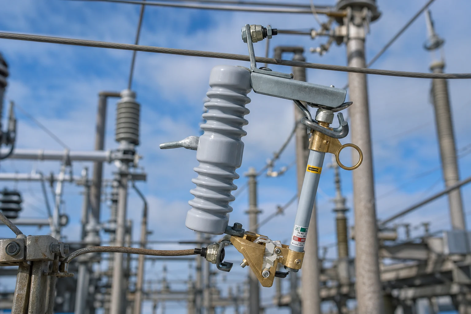
Part 1. Why does 15 kV selection start with the distribution system?
Distribution networks carry a nominal voltage class and an equipment insulation level that may differ from marketing labels on export datasheets. A fuse cutout must remain coordinated with upstream breakers or reclosers, downstream transformer impedance, and the expulsion fuse link that actually clears the fault. IEC 60282-2 covers fuse-switch/disconnector equipment for alternating current; use it to structure the equipment request, not as proof that any catalogue row is automatically approved on your network.
Buyers often search “15 kV fuse cutout” when the engineering file already states a 15 kV class primary or a 12.7 kV line-to-line operating point. Translate that file into equipment inputs before shortlisting cutouts. Where insulator material also matters, see the lateral article on porcelain vs polymer fuse cutouts after duty class is fixed.
| System document | What it supplies to cutout selection |
|---|---|
| Single-line diagram | Placement, upstream protection, downstream asset |
| Protection study / coordination notes | Fault level, fuse speed, selectivity |
| Equipment voltage class definition | Nominal and insulation levels |
| Owner standards list | Named IEC/ANSI or utility equivalents |
Important: A catalogue “15 kV” label does not replace the owner-approved voltage class and insulation level. Source context: IEEE C37.41 distribution cutout scope.
Part 2. How does protection placement change the inputs?
Transformer protection cutouts see different load and fault contributions than lateral line cutouts on the same voltage class. A transformer bay cutout must align with transformer full-load current, inrush considerations, and the downstream fault seen from the primary side. A lateral cutout must coordinate with upstream recloser curves and segment fault levels along the feeder.
For operating sequence and visible isolation behavior, see how a fuse cutout works. Placement changes the continuous current label and the fuse link curve family even when the insulator voltage class stays in the 15 kV band.
Placement-specific questions
- Transformer bay: What is continuous load, energization inrush, and through-fault duty seen at the cutout?
- Lateral tap: What is the maximum available fault current at the tap under parallel feed conditions?
- Capacitor or specialty branch: Are switching surges or back-to-back energization factors included in the study?
- Visibility: Does the owner require loadbreak/disconnect blade options for isolation procedures?
Part 3. Which voltage, BIL, and current inputs must align?
Voltage class drives insulation dimensions. Continuous current drives the cutout base rating and fuse link amp selection. On published FUERTE pages, family tables list 10–15 kV rows with impulse withstand across gaps near 110 kV for FSC-1/HFSC-1 class families—confirm the exact SKU row rather than assuming every 15 kV cutout shares one number.
The FSC-1-1 drop-out fuse cutout product page illustrates how a single SKU can publish 10–15 kV class, 100/200/300 A continuous options, 110 kV impulse, 42 kV power-frequency withstand to earth, and 220 mm creepage on that page only. Do not generalize those figures to polymer HFSC units or other porcelain models such as the FSC-1 family row with 230 mm leakage on the family table.
| Input | Buyer action | Common error |
|---|---|---|
| Nominal / equipment voltage class | Copy from owner diagram and insulation specification | Using export marketing voltage only |
| BIL / impulse withstand | Require value on offered datasheet for the SKU | Assuming 110 kV applies to every “15 kV” cutout |
| Power-frequency withstand | Match to system insulation coordination | Omitting earth vs phase values |
| Continuous current | Size to load plus applicable diversity rules | Picking 100 A because it is catalogued |
| Creepage / leakage distance | Compare to environment class | Ignoring pollution when selecting class |
Part 4. How should available fault level drive cutout and fuse link choice?
Interrupting duty must exceed the maximum fault current the cutout and fuse link pair can see at the installation point, including parallel feeds and temporary switching configurations noted in the study. The published FSC-1-1 page lists 8 kA breaking current for that model—treat it as an example of how one SKU expresses interrupting capability, not as the 15 kV class default for all cutouts.
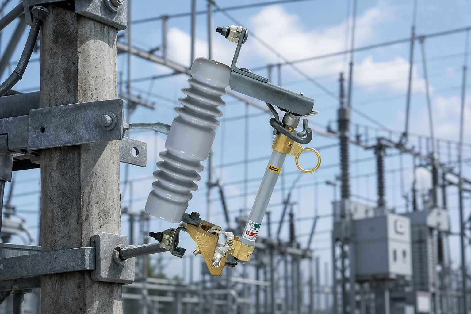
Expulsion fuse links limit what the assembly can interrupt in practice. A cutout nameplate interrupting label does not remove the need to match link type, speed, and manufacturer pairing rules. When fault levels approach table limits, escalate to engineering review with the study file rather than extrapolating from a neighbour feeder.
| Fault study output | Cutout/fuse action |
|---|---|
| Maximum available kA at location | Select cutout + link pair with verified interrupting capability |
| Selectivity requirement with recloser | Choose fuse speed/class per coordination plot |
| Temporary parallel operation | Re-run fault level for switching state |
| Growth margin | Document whether spare interrupting margin is required |
Tip: Attach the fault calculation excerpt for the actual cutout location—not a generic substation bus fault—to the RFQ. Source context: IEEE C37.42 cutout fuse specification scope.
Part 5. What coordination data belongs in the same file?
Cutout selection fails in service when the fuse link is treated as an accessory. Include link amp rating, speed, material class, and manufacturer pairing rules in the same specification bundle as the cutout. The expulsion fuse link selection guide covers link-specific inputs; this article stays on the cutout/system interface.
Coordination also includes mounting hardware: NEMA bracket type, optional disconnect blade, arcing rod, and conductor termination orientation. These mechanical choices affect interchangeability on poles already built to a utility standard.
Coordination bundle
- Cutout SKU with verified voltage, continuous, and interrupting data.
- Matched expulsion fuse link type/size and speed class.
- Upstream device curves (recloser, breaker) showing selectivity intent.
- Single-line diagram snippet with fault levels annotated at the cutout node.
- Any owner rule for visible open gap, loadbreak operations, or grounding practices.
Part 6. Which documents prove a match to the system study?
Procurement should require traceability from system inputs to the offered datasheet and test records. Minimum expectations for a 15 kV class overhead project typically include outline drawings, rating table rows, and test reports applicable to the procured model under the contract standard list.
Do not accept a family-table screenshot as the sole engineering record when the owner requires type tests or routine tests for the exact SKU. When material choice remains open, complete the insulator trade-off review in porcelain vs polymer fuse cutouts before issuing the purchase order.
| Document | Proves |
|---|---|
| Outline drawing | Dimensions, creepage, clearances, bracket interface |
| Rating table row for SKU | Voltage class, continuous current, BIL, interrupting |
| Test reports | Named tests under contract standards |
| Fuse link datasheet | Coordination with cutout family |
| Deviation log | Any exception to owner specification |
Part 7. What should a 15 kV fuse cutout RFQ include?
Use the RFQ to force bidders to respond against the same system file.
RFQ input list
| Buyer should provide | Why it matters | Example | Common mistake |
|---|---|---|---|
| Single-line diagram excerpt | Shows placement and upstream/downstream devices | Transformer primary cutout on 15 kV class feeder | RFQ with no location context |
| Nominal voltage / equipment class | Sets insulation coordination | 15 kV class equipment on 12.7 kV line | Marketing voltage only |
| Continuous load current | Sizes base and link | 130 A continuous transformer load | Using fuse link amp as continuous rating |
| Maximum available fault current | Sizes interrupting duty | 7.8 kA at cutout location | Substation bus fault copied incorrectly |
| Coordination notes | Preserves selectivity | Recloser curve plot | Omitting recloser segment |
| Insulator material preference | Narrows SKU families if decided | Porcelain FSC vs polymer HFSC | Material debate before duty is known |
| Standards and tests required | Enables bid comparison | IEC 60282-2 plus owner supplement | Standard named without test list |
| Delivery and bracket specification | Avoids field mismatch | NEMA A bracket, arcing rod included | Bracket omitted |
Part 8. When is a FUERTE enquiry appropriate?
FUERTE is appropriate when the buyer has the Part 7 RFQ bundle and needs a model-specific quotation on verified pages. Start from the fuse cutout product line, then narrow to families such as the FSC-1-1 drop-out fuse cutout only when that SKU matches the documented duty—remember its published 10–15 kV class, 110 kV impulse, 8 kA breaking current, and 220 mm creepage apply to that product page alone.
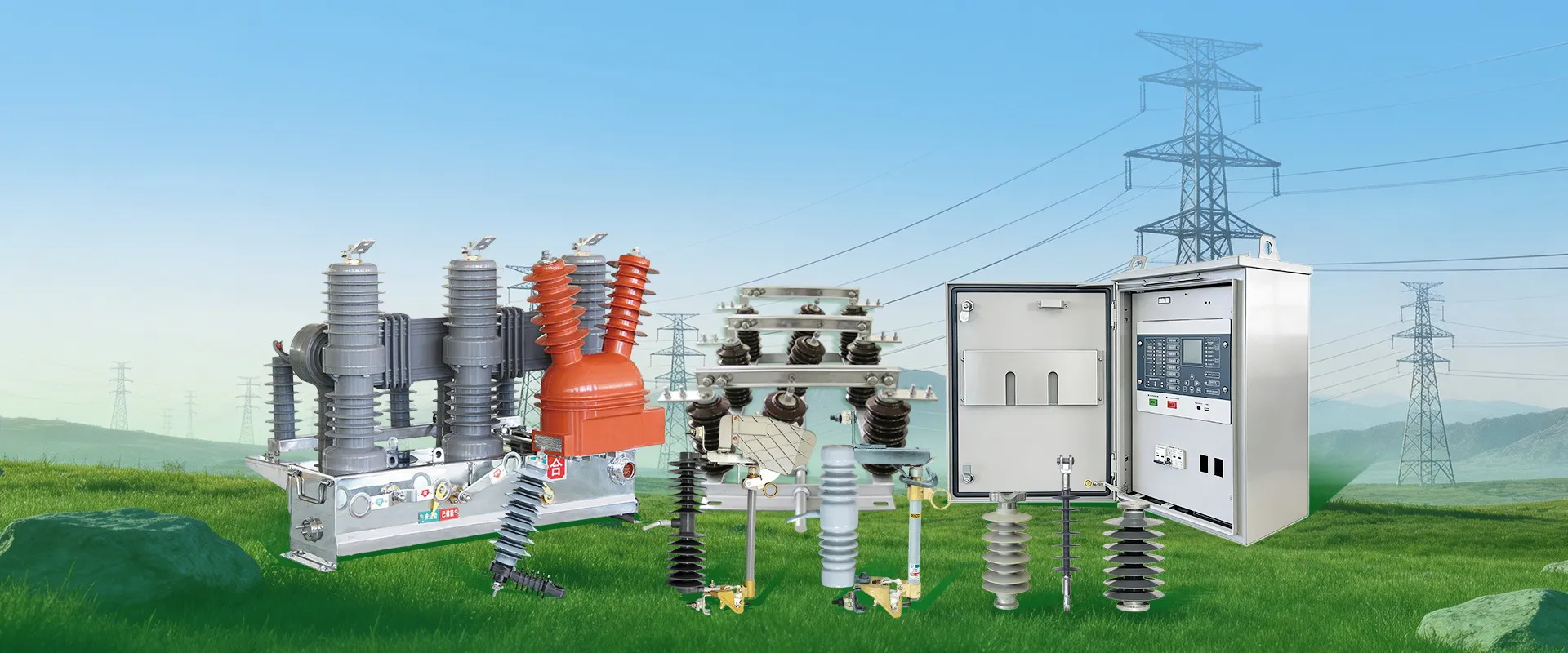
Fit Boundary: No product page replaces the owner engineering study. HFSC polymer SKUs, other FSC family members, and loadbreak variants require their own datasheet rows. FSC-1-1 parameters must not be generalized across the 15 kV class.
Next step: submit the system file through request a fuse cutout quotation with fault levels, coordination notes, and required test documents attached.
FAQ
How do I select a 15 kV fuse cutout for overhead distribution?
Start from the single-line diagram and protection study: define placement, voltage class, continuous current, fault level, and fuse link coordination. Compare SKUs only after those inputs are documented.
Does a catalogue 15 kV label match my system automatically?
No. Export catalogues use convenient voltage bands. The owner-approved equipment class and insulation level from the system specification must match the offered cutout ratings.
What BIL belongs in a 15 kV class cutout request?
Require the impulse withstand across gaps stated on the offered SKU datasheet. Example: the published FSC-1-1 page lists 110 kV impulse for that model only—other SKUs may differ.
How does continuous current affect cutout selection?
Continuous current sizes the cutout base and fuse link amp rating for normal load. It is separate from interrupting duty, which must cover fault current at the installation point.
What fault level must the cutout interrupt?
It must interrupt the maximum fault current calculated at the cutout location for the switching states the owner defines, with an approved fuse link pairing. Use study excerpts, not generic substation values.
Do transformer and lateral applications need the same inputs?
They share voltage class but differ in load, inrush, and fault contributions. Placement-specific coordination drives continuous current and fuse speed even within the same 15 kV class.
Which documents should prove system matching?
Outline drawings, SKU rating rows, applicable test reports, fuse link datasheets, and any deviation log tied to the owner specification prove matching—not catalogue marketing alone.
When should selection go to engineering review?
Escalate when fault levels approach published interrupting limits, selectivity is unclear, parallel feeds change duty, or the owner requires formal coordination sign-off before procurement.
References
- Fuse-switch/disconnector equipment scope: IEC 60282-2
- Distribution cutout and fuse-switch scope: IEEE C37.41
- Cutout fuse specification scope: IEEE C37.42
- Overhead distribution systems context: Utility Products overhead distribution overview
- Electrical insulator fundamentals: Wikipedia insulator overview
- Overhead line work safety scope: OSHA 1910.269