








An arrester’s nominal voltage is not a complete statement of its protection duty. System earthing, temporary overvoltage, the protected equipment’s insulation and the physical lead arrangement can change what the installation requires. Replacing a unit with a higher voltage label may therefore leave the underlying coordination question unresolved. For an industrial grid or distribution project, the buyer needs a defined system study, an installation drawing and product-specific ratings before comparing offers. This guide explains which inputs govern arrester selection, how installation details affect the review and what inspection and documentation should accompany a proposed replacement.
Summary: A power-grid lightning surge arrester must be coordinated with the actual surge sources, system grounding, maximum continuous operating voltage (MCOV), temporary overvoltage, discharge-current duty, insulation level, and installation geometry. IEC 60099-4 covers metal-oxide surge arresters without gaps for AC systems above 1 kV; it is a product and test framework, not a universal approval for every network. Put the single-line diagram, fault and grounding assumptions, protected-equipment insulation data, lead lengths, and required inspection records into the RFQ before comparing models.
Map the Surge Sources and Exposure
Start with the event, not the catalogue. A direct stroke to an overhead line, a nearby strike with inductive coupling, backflashover at a pole or tower, and switching of transformers, capacitors or long cables produce different current amplitudes and front times. A feeder connected to a cable network can also see travelling-wave reflections at a transformer or open end. The arrester diverts the transient current, but the system study must identify where the current can enter and which insulation is most exposed.
Record lightning density or utility experience, overhead-line length, shield-wire and tower earthing arrangements, switching practice, cable transitions, and the location of sensitive transformers, motors, drives and control panels. This information determines whether protection is needed at a line entrance, transformer terminals, a cable transition, or several coordinated points. A surge arrester for power-system overvoltage protection should be treated as one element in an insulation-coordination scheme, not as a stand-alone guarantee against every transient.
| Внесение предложений по дизайну | Инженерный вопрос | Evidence for the RFQ |
|---|---|---|
| Surge source and path | Is the dominant exposure lightning, switching, backflashover or cable reflection? | Single-line diagram, line route, utility event history and grounding study |
| System voltage and grounding | What line-to-ground voltage can the arrester see during normal and earth-fault conditions? | Nominal and maximum system voltage, neutral treatment and fault-clearing time |
| Protected insulation | Is the arrester residual voltage below the equipment withstand level with coordination margin? | Transformer, cable and switchgear impulse-withstand data; coordination calculation |
| Окружающая среда и механика | Will pollution, altitude, salt, wind, ice or vibration change clearances or housing stress? | Site survey, pollution class, altitude, ambient range and mounting drawing |
Match MCOV, Grounding and Energy Duty
MCOV, often marked Uc, is the highest RMS power-frequency voltage intended to be applied continuously across the arrester. It must be checked against the maximum operating voltage and the system’s grounding arrangement. During a single-line-to-ground fault, an effectively grounded network may limit the healthy-phase rise differently from an isolated or impedance-grounded network. Temporary overvoltage magnitude and duration therefore belong in the selection calculation; nominal voltage alone is not enough.
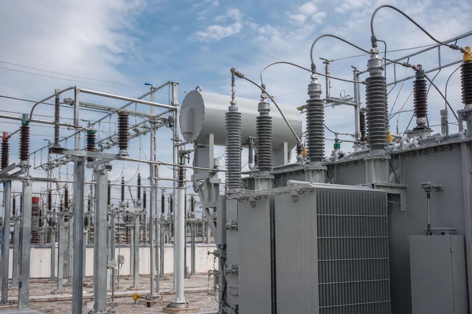
Rated voltage, Ur, is related but not interchangeable with MCOV. Ask the manufacturer for the temporary-overvoltage withstand curve and the assumptions used to derive the recommended Ur/Uc pair. Then compare the nominal discharge current (commonly specified with an 8/20 us impulse), line-discharge or switching-duty class, and energy-handling evidence with the actual network. A larger nominal discharge-current label may be unnecessary if the duty study does not support it, while a low-duty unit can be overstressed by repeated switching or a high-energy line discharge.
The metal-oxide varistor (MOV) blocks are the non-linear element that conducts during a surge. Their reference voltage, leakage-current stability, thermal behaviour and impulse energy capability must be supported by controlled routine and design-test records. The visible polymer housing cannot prove the internal MOV grade; request the exact model’s data rather than extrapolating from a similar-looking metal-oxide surge arrester.
Coordinate Insulation and Installation
Insulation coordination is a voltage comparison with a physical layout. Use the arrester’s residual-voltage values at the relevant impulse current and compare them with the protected equipment’s lightning impulse withstand level, allowing the project margin required by the utility or design standard. Pollution and altitude can change external insulation requirements; guidance such as IEC TS 60815-1 helps structure the environmental assessment, but the project still needs its own clearances and creepage calculation.

Keep phase and earth connections short, straight and separated from other conductors. The inductive voltage produced by a long or looping lead is added to the arrester residual voltage, so an arrester mounted far from a transformer bushing may provide a weaker clamp at the equipment than its datasheet suggests. Record the one-way phase lead, earth lead, bends, and bonding point on the installation drawing. Bond the arrester to the same low-impedance earthing reference used by the protected equipment, following the site’s safe isolation and earthing procedure.
For outdoor assemblies, verify terminal load, bracket strength, disconnector clearance, line hardware, and maintenance access. Do not add a counter, disconnector or insulating base unless its ratings and mechanical interface are documented for the exact arrester. A polymer-housed arrester option may suit a particular environment, but its creepage, sealing and hardware details must be reviewed against the site conditions.
Monitor, Inspect and Document the Purchase
Monitoring is useful only when the baseline and response are defined. Where a leakage-current monitor or surge counter is specified, record its normal reading after commissioning, confirm the measurement method, and set an inspection trigger with the responsible operator. A rising resistive-current component, repeated counter operations, cracked housing, damaged sheds, contamination, or a disconnector indication should prompt a controlled outage inspection. A counter reading by itself does not identify the cause of failure.
Common failure modes include MCOV selected below the actual continuous stress, thermal runaway after repeated energy events, moisture ingress or seal damage, surface pollution and tracking, mechanical cracking, loose terminals, and excessive lead inductance. Investigate the event record, phase voltages, earth-fault history, weather, switching operations, installation geometry and test evidence before replacing the unit. Do not infer a service duration or claim that any arrester provides total protection; condition and duty determine what can be concluded.
| Observed condition | Likely check | Evidence or action |
|---|---|---|
| High or rising leakage current | MCOV/TOV assumption, contamination, moisture, MOV ageing or monitor method | Baseline and trend record, thermographic or approved diagnostic review |
| Flashover or tracking | Pollution, creepage, damaged sheds, clearance or earthing path | Site condition report, wash/maintenance record and installation drawing |
| Arrester operated after a storm or switching event | Surge source, energy duty, counter indication and disconnector status | Event log, weather or switching record, removed-unit quarantine and test plan |
| Unexpected equipment damage | Residual voltage, lead length, bonding point and insulation margin | Coordination calculation, dimensional check and approved corrective drawing |
For procurement, request a controlled datasheet, dimensional and mounting drawing, Uc/Ur and TOV information, residual-voltage table, discharge-current and energy-duty data, routine-test scope, design/type-test report for the exact design, monitoring-accessory details, installation instructions, packing and traceability records. IEC 60099-4 is the relevant official reference for gapless metal-oxide arresters in AC systems; the IEC 60099-4 publication page defines its scope. It does not replace a utility’s approved list, a project specification, or an inspection of the supplied nameplate and documents. For a project-specific quote, the surge arrester product range can be reviewed against the same evidence checklist.
ЧаВо
What is the difference between MCOV and rated voltage?
MCOV (Uc) is the continuous RMS voltage the arrester is intended to withstand in service. Rated voltage (Ur) is used with the specified temporary-overvoltage duty for a defined time. Select both from the system’s maximum voltage, grounding and fault-clearing assumptions; do not infer either value from nominal voltage alone.
Is a 20 kA arrester automatically better than a 10 kA arrester?
No. Nominal discharge current is one part of the duty calculation, and the relevant impulse waveform, line-discharge or switching energy, system exposure and insulation coordination must also be checked. Choose the tested duty that matches the application and the utility or project requirement.
How short should arrester leads be?
There is no single universal length. Keep phase and earth conductors as short, straight and direct as the installation allows, then verify the resulting inductive contribution in the coordination calculation. The drawing should show actual lead lengths and bends, not just a symbol for the arrester.
What causes a surge arrester to fail after a storm?
Possible causes include an energy event above the design duty, excessive temporary overvoltage, moisture ingress, contamination, a poor earth path or a prior damaged MOV block. Preserve the removed unit, record the event and inspect the installation before selecting a replacement.
Does IEC 60099-4 certify every arrester for every grid?
No. IEC 60099-4 sets requirements and test methods for a defined class of gapless metal-oxide arresters. Acceptance still depends on the exact design evidence, destination utility rules, system conditions, installation and the documents supplied with the unit.
Выводы
Reliable arrester selection is an insulation-coordination and installation exercise, not a race to the largest catalogue rating. Map the lightning and switching sources, confirm MCOV and temporary-overvoltage duty for the grounding arrangement, then compare residual voltage and energy evidence with the protected equipment’s withstand level. Keep phase and earth leads short, document the bonding path, and define how leakage current, counters, disconnectors and visual condition will be inspected. In the purchase package, require the exact model’s drawings, Uc/Ur, duty data, test scope and traceability; treat IEC 60099-4 as the applicable technical framework, not as a universal network approval. When a unit operates, preserve the evidence and investigate before replacement. That discipline helps buyers reduce avoidable outages while keeping technical claims proportional to the data available. Contact FUERTE with the single-line diagram, grounding method, equipment insulation data and site conditions for a project review.