
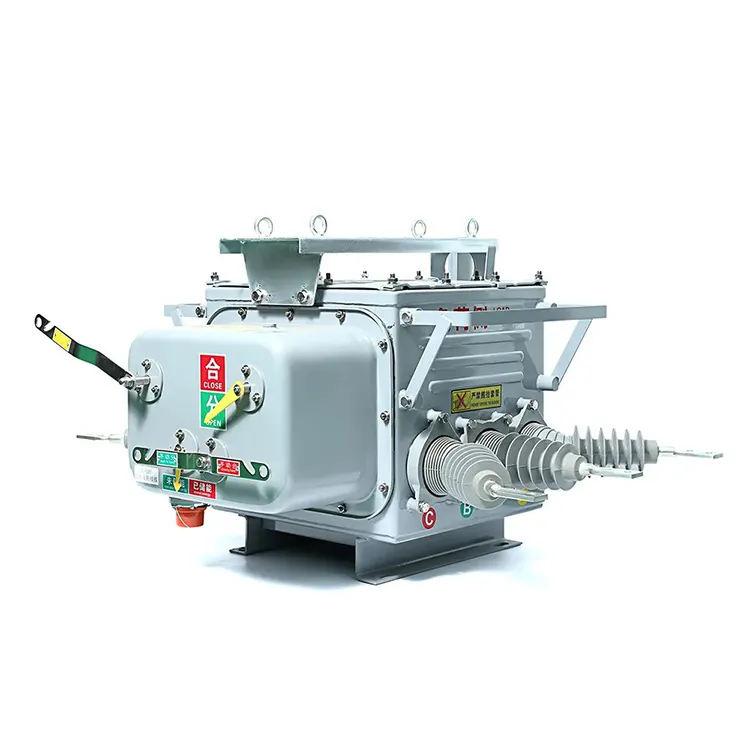
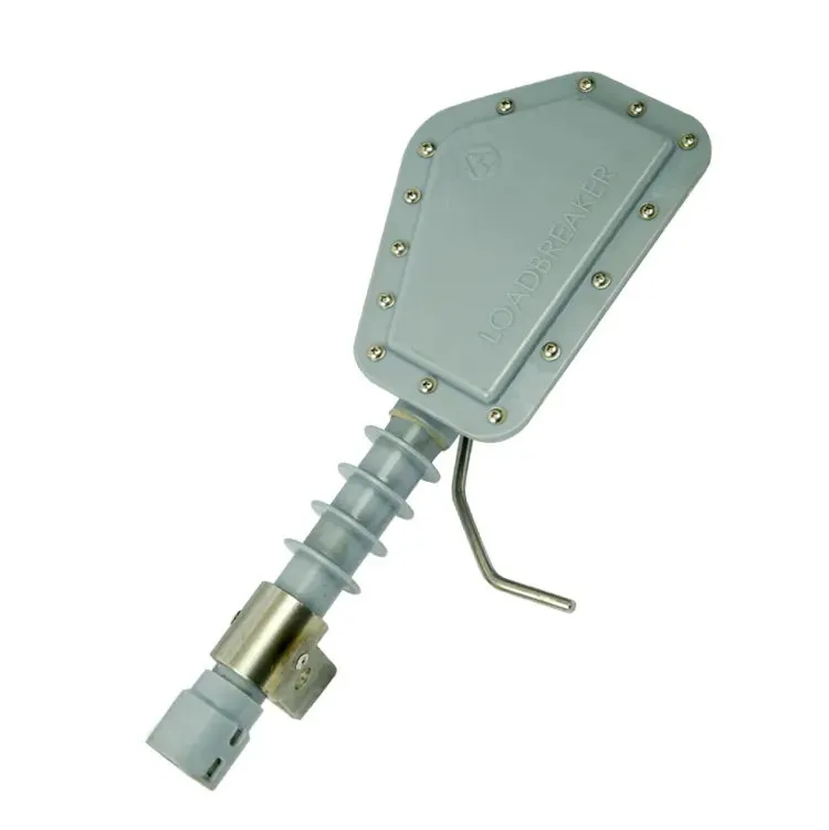


A substation layout can be neat and still be based on incomplete requirements. If fault data arrive after equipment selection, or access needs are checked after foundations are fixed, the drawing may need expensive changes. The problem is often the order of decisions rather than the appearance of the design. Electrical duties, operating requirements and site conditions need to be established before equipment dimensions become the centre of the project. This article follows that sequence from the design basis to construction and commissioning, with particular attention to the interfaces where a technically correct component can still be wrong for the installation.
Substation design starts with the network connection, voltage levels, load, fault conditions, operating policy and site constraints. These inputs support the system studies and single-line arrangement, which then guide equipment selection and physical layout. Civil and electrical teams must reconcile actual equipment interfaces before construction is committed. Commissioning depends on approved drawings, settings, procedures and the required inspection and test records. No generic layout can establish all of these requirements. For example, US 29 CFR 1910.303 ties interrupting equipment to the available fault current, illustrating why a system input must precede a product choice.
What information should start a substation design?
The design basis should describe the connection, expected present and future load, reliability requirements, fault data, grounding arrangement and environmental conditions. Identify who owns each input and which version has been approved. Where a value is provisional, record the decision it affects and when confirmation is needed.
EIA’s overview of electricity delivery places substations within the wider network. That context matters: a design cannot determine upstream supply conditions or downstream operating obligations solely from the site boundary. The transmission and distribution guide explains these functional boundaries.
| Design input | Decision it supports | What should be documented |
|---|---|---|
| Load forecast | Capacity and development stages | Demand assumptions, diversity and relevant contingencies |
| Fault study | Interrupting and withstand duties | Network configuration and study basis |
| Operating requirements | Bus arrangement and maintenance provisions | Permitted outages and continuity expectations |
| Site conditions | Equipment and civil design | Applicable environmental and ground information |
| Connection requirements | Protection, control and utility interfaces | Responsible parties and approved interface details |
How do load and fault studies change equipment selection?
Load and fault current answer different questions. Load assessment supports normal and contingency operating duties. A short-circuit study establishes fault conditions relevant to interrupting, withstand and protection requirements. A continuous-current rating is not a fault-interruption rating, even when both use amperes.
29 CFR 1910.303 requires equipment intended to interrupt fault current to have a sufficient interrupting rating for the nominal circuit voltage and available current at its terminals in the US installations within its scope. The project must also establish the applicable product and utility requirements. Naming a standard family does not prove that a particular model or configuration complies.
Use the study results to populate equipment schedules, then check the supplier’s actual ratings and evidence. A circuit breaker nameplate review helps distinguish the values that are easy to confuse. Future network changes should be included where they form part of the approved design basis, rather than covered by an unexplained margin.
What must civil and electrical teams coordinate?
The general arrangement must accommodate the electrical design and the real equipment. Confirm base dimensions, mounting interfaces, loads, cable or conductor routes, access and replacement needs. The relevant equipment drawings must be approved before relying on them for foundations or penetrations.
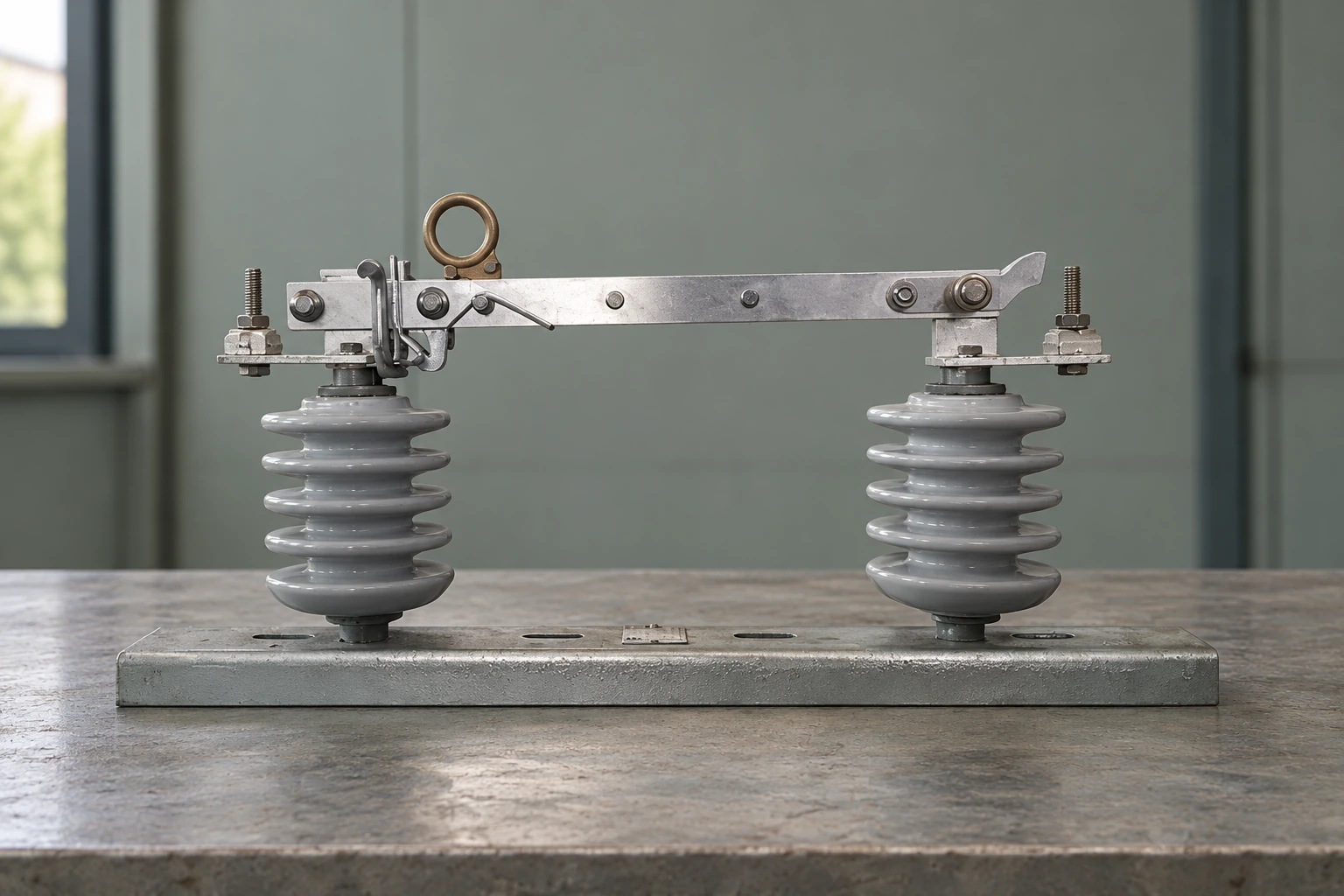
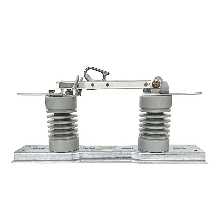
The original switch’s visible base illustrates why an equipment interface matters; it does not provide foundation dimensions or structural loads. Those belong in the manufacturer’s drawing and the project’s civil design. An image or catalogue outline cannot substitute for the required dimensional information.
| Interface | Electrical-side question | Civil or construction-side question |
|---|---|---|
| Equipment support | Which approved model and mounting arrangement? | Which loads, dimensions and fixing requirements apply? |
| Cable and conductor routes | Which circuits and connection interfaces? | Where are routes, entries and installation access provided? |
| Maintenance access | Which equipment may need isolation or replacement? | Can personnel and replacement equipment reach it? |
| Drainage and environment | Which exposure limits and equipment provisions? | How are site water and ground conditions managed? |
| Expansion area | What future circuits and studies are assumed? | Which foundations, routes and access provisions are reserved? |
How are insulation and grounding requirements established?
Insulation requirements follow the system voltage, expected stresses, environmental conditions and applicable design criteria. Grounding design needs the system and site information relevant to fault conditions and personnel protection. Neither should be reduced to a clearance copied from another project or a generic target resistance without its design context.
The substation design overview identifies both electrical and physical planning considerations. A project-specific design still requires competent engineering under the applicable standards and utility rules. This article does not prescribe installation dimensions or an operating procedure.
Which records must be complete before commissioning?
Commissioning is not just the final operation of a breaker. The responsible team needs approved drawings, equipment data, protection settings, inspection records, relevant test results and procedures defining responsibilities and acceptance criteria. The records should identify the equipment and document revisions to which they apply.
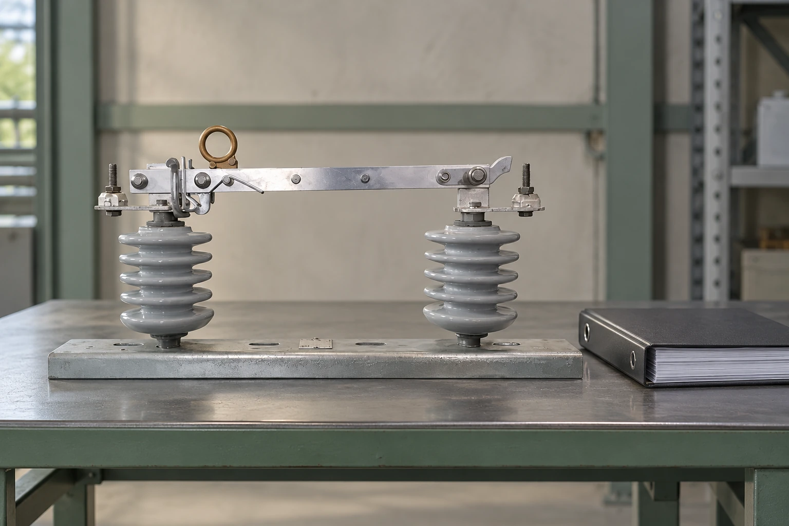
Use document revision control from procurement onward. If a supplied device or interface changes, update the drawings and review the affected settings and procedures. A test record for the previous configuration cannot automatically close out the new one.
Construction and testing near electrical equipment also require the applicable work controls. 29 CFR 1910.269 provides a US electric-power-work context, including qualified personnel and de-energization requirements. The site’s approved procedures and local legal requirements govern actual work; a generic checklist is not authorization to energize.
Frequently asked questions
What information starts a substation design?
Begin with the network connection, voltage levels, expected load, fault data, reliability requirements and site conditions. Assign ownership and approval status to each input so that provisional assumptions are visible.
How do load forecasts affect equipment sizing?
They establish the demand that equipment must serve under the agreed operating conditions and development stages. Sizing should reflect documented assumptions and relevant contingencies rather than an arbitrary percentage added to current demand.
Why is a short-circuit study needed?
It establishes fault conditions used to assess equipment interruption, withstand and protection duties. A normal-current rating cannot substitute for this information.
Which environmental conditions affect the layout?
Relevant conditions may include temperature, altitude, pollution, moisture, flooding, wind, seismic requirements and ground conditions. The project must identify which apply and obtain the corresponding site data.
How are insulation and grounding requirements established?
They are derived from system studies, site conditions and the applicable utility, product and installation requirements. Neither a generic clearance nor an isolated resistance value is a complete design basis.
What is checked during civil and electrical coordination?
Teams reconcile the actual equipment dimensions, loads, mounting details, cable routes, access, drainage and replacement needs. These checks must use the approved equipment and drawing revisions.
How should future expansion be considered?
Define the intended future circuits and operating conditions, then reserve the necessary electrical and physical provisions. Empty land alone does not establish that busbars, protection, auxiliary systems or fault duties can accommodate expansion.
Which documents are needed before commissioning?
The required set generally includes approved drawings, equipment records, protection settings, inspection and test documentation, and commissioning procedures with acceptance criteria. The responsible project team must confirm completeness for the actual installed configuration.
References
Sources checked on 2 November 2026.
- US Energy Information Administration — Delivery of electricity to consumers
- 29 CFR 1910.303 — Electrical installation requirements (Cornell LII)
- Wikipedia — Electrical substation: functions and design
- 29 CFR 1910.269 — Electric power generation, transmission and distribution (Cornell LII)
Summary
A workable substation design carries the same agreed requirements from system studies through equipment selection, construction and commissioning. Start with load, fault and operating conditions, then establish the circuit arrangement and equipment duties. Coordinate the real physical interfaces before fixing the civil design, and keep revisions aligned when something changes. Expansion assumptions and commissioning evidence need the same discipline as the initial purchase specification. A correct-looking layout cannot compensate for an unresolved system input or an obsolete drawing. Fuerte’s isolating switch products can be reviewed for a defined project role once the electrical duty, mounting interface and required documentation are clear. Request model-specific evidence against those requirements before committing the equipment to the design.