








Two structural families cover almost every arrester a medium-voltage buyer will meet. The gapless surge arrester connects its zinc oxide varistor column straight between line and earth, while gapped structures place series spark gaps in front of their internal elements. That one structural decision shapes how the device lives at system voltage, how it responds to overvoltages, how it is monitored, and what suppliers actually offer for new projects.
This guide treats the choice as an application question for MV systems: what each structure does in service, which inputs decide a purchase, and how to use product context responsibly. It does not retell the material history of older element types, select an arrester for a specific transformer, or replace an insulation-coordination study.
What gapless and gapped mean in an arrester structure?
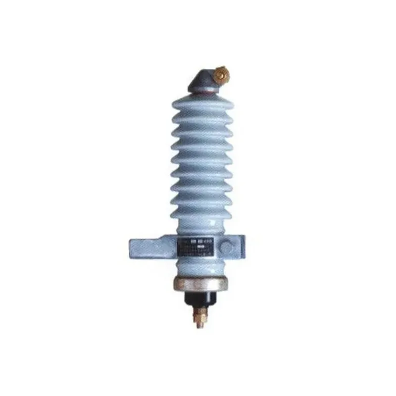
Strip away housings and brackets, and an arrester is a column of voltage-dependent elements between a line terminal and an earth terminal. In a gapless design that column — zinc oxide varistor blocks in modern products — faces the system directly, with no other series element. Background references such as the Wikipedia surge arrester overview describe this as the standard structure of current metal-oxide arresters. For a related technical topic, see Metal-Oxide vs Silicon Carbide Lightning Arresters: A Technical Comparison.
A gapped structure adds one or more spark gaps in series with the internal elements. At normal voltage the gaps insulate, so the elements see no continuous stress; the device only connects to the circuit when an overvoltage causes sparkover across the gap stack.
Some later designs also combined small gaps with metal-oxide blocks for particular coordination goals, which is why “gapped” describes a structure rather than one specific product generation. For an MV buyer, the structural label is the fastest way to understand how a unit behaves before reading any rating table.
How should buyers life at system voltage: energization and leakage current?
A gapless column is energized every hour the feeder is live. Zinc oxide blocks make that workable because of their extreme nonlinearity, described in plain language in the Wikipedia varistor article: at continuous operating voltage they pass only a small leakage current, and they move into conduction as voltage rises.
Because the column is always connected, continuous-voltage duty becomes a first-class rating question. The unit’s maximum continuous operating voltage must cover the system’s actual phase-to-earth voltage, including how the earthing arrangement behaves during faults, and temporary overvoltages must be reviewed against the manufacturer’s data for the exact SKU.
Leakage current also becomes an asset-health signal. A rising resistive leakage component over years of service is one of the indicators maintenance teams watch, which is why monitoring accessories exist for gapless fleets.
Why gapped structures existed and what the gaps had to do?
Series gaps solved a materials problem from an earlier product era. Element materials that preceded modern varistor ceramics conducted too much at normal system voltage to stay connected continuously, so the gap stack held them off the line and connected them only during sparkover events.
That structure bought isolation at a price. The gaps had to spark over reliably at the intended level, then interrupt the power-frequency follow current after each operation, and their behavior depended on gap condition, grading components, and sealing over the years.
For selection purposes today, the detail that matters is the service consequence: a gapped structure responds only after sparkover, while a gapless column limits voltage progressively as the surge develops. The deeper material-generation story sits outside this page’s scope; here it is enough to know why the gaps existed and what duty they carried.
How should buyers selection considerations: how structure changes service behavior?
Structure is not an abstract preference; it changes what the device does on the pole or in the bay. The comparison below keeps the view at the service level rather than the laboratory level.
| Service aspect | Gapless structure | Gapped structure |
|---|---|---|
| State at normal voltage | Column energized continuously with small leakage | Elements isolated behind non-conducting gaps |
| Overvoltage response | Progressive conduction as voltage rises | Sparkover first, then element conduction |
| After an operation | Column returns to high-resistance state on its own | Gaps must clear follow current to reset |
| Continuous-voltage rating focus | Maximum continuous operating voltage and temporary-overvoltage review | Sparkover setting and gap condition |
| Condition monitoring | Leakage indicators, discharge counters, disconnectors are common accessories | Gap condition hard to observe in service |
| Weather and aging sensitivity | Housing and sealing condition dominate | Gap behavior adds a further variable |
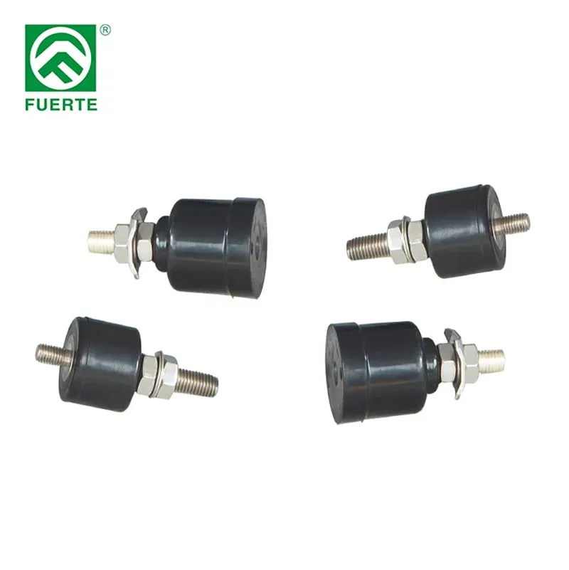
Monitoring deserves emphasis for gapless fleets. Leakage-current indicators and discharge counters give operations teams a view of arrester condition without de-energizing, and disconnector accessories separate a failed unit from the line; the owner’s maintenance philosophy decides which of these the specification requests.
No row in that table assigns numbers to any product. Ratings, leakage limits, and accessory scope are SKU-level data that belong to the exact product documentation.
How should buyers mV application scenarios and the inputs that decide?
Application context turns the structural comparison into a purchase decision. The same feeder questions come up in almost every MV inquiry, and collecting them before the quotation avoids a second round of clarification.
| Application input | Why it matters | Typical evidence |
|---|---|---|
| System voltage and earthing arrangement | Sets continuous-voltage duty for an energized column | Network owner’s system data |
| Temporary-overvoltage conditions | Stress events the continuous rating must survive | System-study extract where available |
| Installed position | Line structures, equipment terminals, and cable interfaces stress arresters differently | Layout or pole drawing |
| Energy duty questions | Discharge duty expectations belong in the engineering review | Owner’s design basis |
| Accessories and monitoring scope | Brackets, disconnectors, counters, and indicators vary by fleet practice | Maintenance philosophy notes |
| Documentation requirements | Comparable offers need the same requested evidence | Procurement specification |
Where the protected asset is a distribution transformer, hand the case to the dedicated guide on metal-oxide surge arrester selection for distribution transformers; this page deliberately stops at the structural and application view. Naming questions — arrester versus lightning arrester wording in tender documents — are covered once in the difference between surge arrester and lightning arrester.
How should buyers availability, renewals, and what to specify today?
Catalog reality is part of selection. Modern MV distribution ranges, including the FUERTE lightning arrester family, are built around gapless metal-oxide construction, and the governing product standard for that type is IEC 60099-4. Gapped units mostly enter conversations as legacy installed base found during audits and renewals.
Renewal specifications therefore usually state a gapless metal-oxide arrester and focus effort on the application inputs from Part 5 rather than on reproducing the legacy unit’s structure. Copying an old nameplate into a new specification is the common mistake; the legacy data is an input for review, not a selection result.
Industry standards pages such as the NEMA surge arrester standards overview provide additional terminology context when specifications must name standards families. Standard references in a specification describe the review basis; they are not a compliance claim by this article for any product.
How should buyers product context and inquiry evidence?
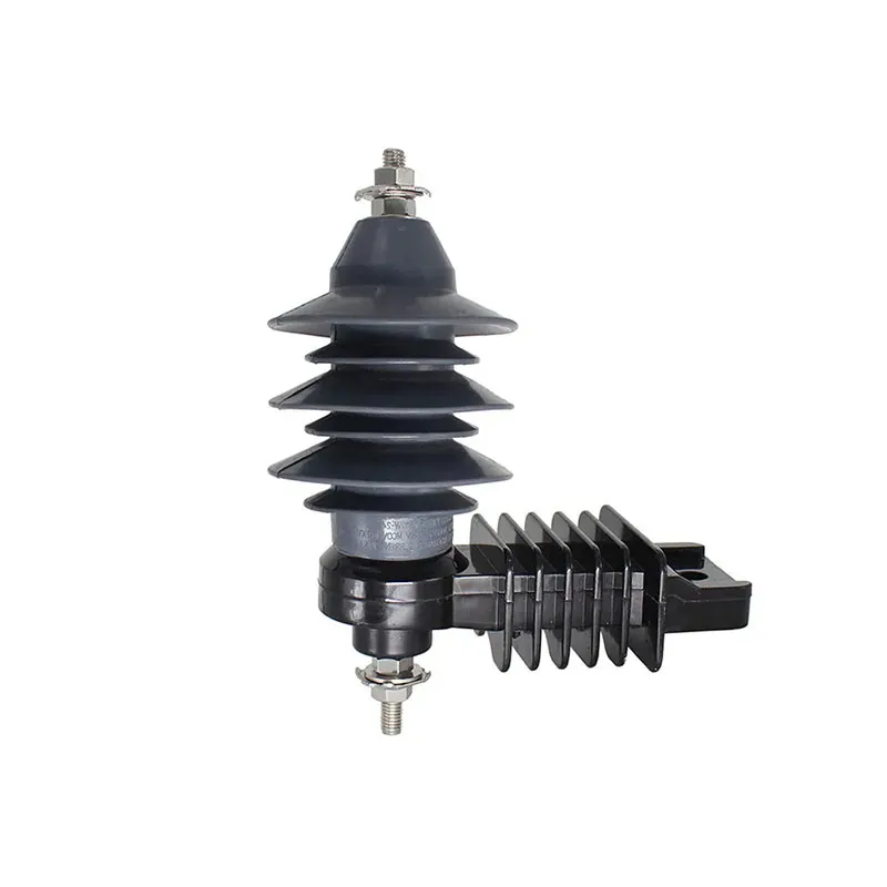
For a concrete gapless example in the lower MV range, the YH510W-9 / YH510W-9J surge arrester product page lists a rated voltage of 9 kV, a maximum continuous operating voltage of 7.65 kV, nominal discharge current options of 5 kA and 10 kA, gapless zinc oxide construction in a polymer housing, and IEC 60099-4:2014 as the referenced standard for the family.
Treat those as the page’s published family values and nothing more. They do not establish fit for a particular feeder, temporary-overvoltage duty, or project, so this is bounded product context rather than a universal product recommendation; the exact SKU documentation and the owner’s engineering review complete the decision.
A complete inquiry through the FUERTE contact route should carry the system voltage and earthing arrangement, temporary-overvoltage information where available, installed position, requested ratings and accessories, quantities, and documentation requirements. With those inputs stated once, every supplier answers the same question and the offers stay comparable.
A useful 2026 review adds one evidence checkpoint that many legacy articles omit: the standard edition and the voltage terminology must be recorded together. IEC 60099-4 is the relevant reference for metal-oxide arresters on AC circuits above 1 kV, while MCOV, rated voltage, temporary overvoltage exposure, residual voltage and energy duty answer different questions. A catalogue number therefore cannot replace the owner’s insulation-coordination basis. Record the source document, revision date and the system earthing assumption beside every value in the RFQ.
The same discipline applies to physical installation. Lead length, earth routing, equipment separation and the actual protected terminal can change the engineering review even when two offers carry the same nominal voltage label. Current search results repeatedly surface MCOV, TOV, residual-voltage and energy questions, but those are prompts for verification, not universal setpoints. Buyers should ask suppliers to identify the test report, declared standard edition, drawing revision and unresolved project input rather than turning a general guide into a guaranteed protection claim.
FAQ
What is a gapless surge arrester?
It is an arrester whose zinc oxide varistor column connects directly between line and earth with no series spark gap. The column is energized continuously, passes a small leakage current at normal voltage, and conducts progressively when an overvoltage arrives.
Do gapless arresters draw current all the time?
A small leakage current flows whenever the system is live, which is normal for the structure. Trends in that leakage over time are one of the condition signals maintenance teams monitor on gapless fleets.
Why did older arrester structures include series gaps?
Earlier element materials conducted too much at normal system voltage to stay permanently connected. Series gaps isolated the elements until sparkover and then had to interrupt the follow current after each operation.
Are gapped arresters still available for MV systems?
Current MV distribution catalogs are built around gapless metal-oxide designs, and gapped units appear mainly as legacy installed base. Confirm availability with suppliers rather than assuming a catalog still carries gapped structures.
How are gapless arresters monitored in service?
Common practice uses leakage-current indicators, discharge counters, and disconnector accessories, chosen according to the owner’s maintenance philosophy. The specification should state which monitoring scope the fleet requires.
Which inputs drive arrester selection for an MV system?
System voltage and earthing arrangement, temporary-overvoltage conditions, installed position, energy duty questions, accessory and monitoring scope, and documentation requirements. Those inputs, not structure alone, turn a comparison into a selection.
Does this article select an arrester for a distribution transformer?
No. Transformer-terminal selection has its own published guide, and this page stops at the structural and application view for MV systems generally.
What should a 2026 surge-arrester RFQ record first?
Start with the protected interface, system voltage and earthing arrangement, continuous-voltage requirement, temporary-overvoltage exposure, installation drawing and requested standard edition. Ask the supplier to identify each source document and every unresolved project input. A nominal voltage label alone cannot establish the correct device or a protection outcome.
Does MCOV by itself select a metal-oxide arrester?
No. MCOV describes the maximum continuous power-frequency operating voltage in the relevant terminology, but selection also depends on system earthing, temporary overvoltage, insulation coordination, discharge duty, residual-voltage evidence and installation geometry. The owner or EPC study should control the final values; the article provides a review path rather than a universal rating table.
Why should lead routing appear in the arrester review?
The arrester protects at its connection point, so the conductor and earth paths form part of the physical protection arrangement. Length, bends, separation and routing can change the voltage seen at the protected terminal. Record the proposed layout and ask for a drawing-based review instead of assuming that two devices with the same catalogue voltage have identical installed behavior.
References
- IEC 60099-4, Metal-oxide surge arresters for AC power circuits above 1 kVOfficial IEC scope and test-standard reference; accessed 2026-10-08.
- NEMA surge arrester standardsStandards-navigation reference for arrester terminology and application; accessed 2026-10-08.
- PSCAD metal-oxide surge arrester referenceDefines MCOV in modelling context; project values remain to be confirmed.
- Surge arrester selection: MCOV, voltage and energyCurrent SERP topic signal for buyer questions; numeric claims require project evidence.