








Illustrative scenario: When Priya, a plant electrical engineer in Pune, approved a motor-feeder replacement, the crew installed a vacuum device that fitted the cubicle. Repeated trips and a damaged upstream fuse appeared during the first production starts. The device was not defective: the specification had treated a frequent-operation contactor and a fault-interrupting breaker as interchangeable, without coordinating motor duty or protection.
Резюме: A vacuum contactor controls frequently switched loads such as motors; a vacuum circuit breaker makes, carries and interrupts normal current and specified fault current. Above 1 kV, compare contactors under IEC 62271-106 and breakers under IEC 62271-100, then verify the lineup under IEC 62271-200. Select by operating duty and protection study—not by vacuum technology or fit alone.
Both extinguish an arc inside a sealed vacuum interrupter, but they do not have the same job. Search terms such as vacuum circuit breaker vcb blur categories; procurement should distinguish operating endurance, fault interruption and protection interfaces.
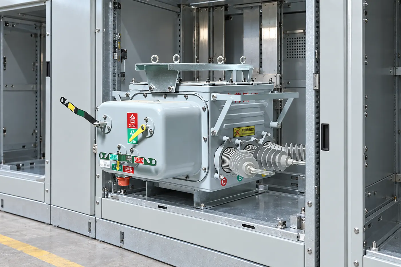
How vacuum contactors and VCBs perform different jobs
A vacuum contactor opens and closes a controlled load. It is normally chosen where frequent starts, stops or process operations matter, so its coil, latch and control scheme are central. IEC 62271-106 covers AC contactors, contactor-based controllers and motor-starters above 1 kV and through 52 kV.
A circuit breaker performs normal switching and interrupts short-circuit duties assigned by the protection design. IEC 62271-100 applies to AC circuit-breakers above 1 kV and addresses dielectric performance, temperature rise, short-circuit making and breaking, and operating sequences. IEEE projects may use IEEE C37.04 ratings and C37.09 test procedures.
The distinction is purpose, not appearance. A contactor may deliver the desired motor-switching endurance yet depend on fuses or an upstream breaker for high fault currents. A вакуумный выключатель combines interrupters, mechanism, insulation and controls for declared breaker duties.
| Размер решения | Vacuum contactor unit | Вытяжной выключатель |
|---|---|---|
| Основная цель | Frequent operational control of a defined load | Feeder switching and protection against assigned faults |
| Typical control context | Motor starter, capacitor or process-load controller | Incoming, bus-section, transformer, motor or distribution feeder |
| Short-circuit role | Usually coordinated with fuses or another protective device; verify the declared controller rating | Interrupts fault current within its rated making and breaking duties |
| Operating pattern | Selected for frequent load operations and utilization category | Selected for protection duty, operating sequence and required endurance |
| Интерфейс защиты | Overload relay plus coordinated short-circuit protection | Protection relay and trip circuit act directly on the breaker |
| Maintenance focus | Coil, latch, auxiliaries, mechanism and contact wear | Mechanism, trip/close circuits, timing, resistance, insulation and interlocks |
| Ценовая тенденция | Can be efficient for frequent control when the protection package is included | Can reduce the need for a separate fault-interrupting device at feeder level |
| TCO boundary | Contactor, fuses or breaker, relay, spares and fuse replacement downtime | Breaker, relay, commissioning, maintenance and spare strategy |
Should a motor feeder use a vacuum contactor or a VCB?
What load-duty data determines the right device?
For a motor feeder, document voltage, full-load and starting current, start duration, starts per hour, reversing duty, stalled-rotor withstand and control sequence. IEC 62271-106 utilization categories and controller characteristics help determine whether a contactor starter suits the pattern. Do not infer endurance from continuous-current rating.
A breaker can protect a motor feeder, but frequent switching may consume mechanism operations or impose other duties. Conversely, a contactor selected for repetitive control cannot be assumed to clear the bus fault. Obtain declared ratings, limits and coordination data for the exact protection combination.
How should the fault-clearing chain be coordinated?
The protection study should compare prospective short-circuit current at the installation point with the interrupting capability of the protective device. It should also coordinate overload, locked-rotor and short-circuit functions so that starting current does not cause nuisance operation while cables and motor thermal limits remain protected. For a breaker feeder, review rated short-circuit breaking current, making current, short-time withstand duty and operating sequence; the vcb circuit breaker breaking-capacity guide explains these distinctions.
For a fused contactor, review fuse time-current behavior, contactor/controller short-circuit rating, let-through energy, relay curve and the manufacturer’s tested coordination arrangement. A fuse may interrupt the high-current fault while the contactor and overload relay handle operational switching and lower-current abnormal conditions. Substituting a fuse, relay or contactor can invalidate the documented coordination even when each component has an acceptable individual nameplate.
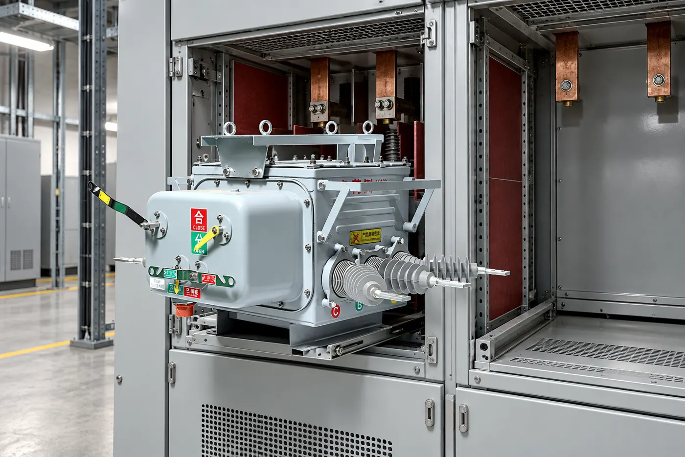
What must buyers compare beyond device current ratings?
Never compare the devices by amperes alone. Confirm system voltage, frequency, continuous current, dielectric withstand, switching and fault duty, endurance, control voltage, auxiliaries and service conditions. Altitude, temperature, humidity and pollution can affect insulation or derating; require stated limits.
| Размер приложения | Often favors a contactor-based controller | Often favors a VCB | Доказательства для запроса |
|---|---|---|---|
| Frequent motor starts | Repetitive operational switching is the dominant duty | Fault protection or infrequent isolation dominates | Starts-per-hour profile, utilization category, endurance declaration |
| High available fault current | Only with a tested, coordinated fuse or breaker arrangement | When its declared interrupting rating covers the study duty | Fault study, coordination curves and type-test basis |
| Process continuity | Fast replacement of fuses/units may be planned | Reset and protection diagnostics may support restoration | Spare strategy, access plan and restoration procedure |
| Existing lineup | Useful where the controller cell, bus and interlocks are verified | Useful where a compatible breaker compartment and relay scheme exist | Drawings, dimensions, primary/secondary interfaces and interlock logic |
| Lifecycle cost | Include fuses, contactor wear, coil energy and replacement labor | Include relay tests, mechanism service and breaker test program | Maintenance manual, parts list and site labor assumptions |
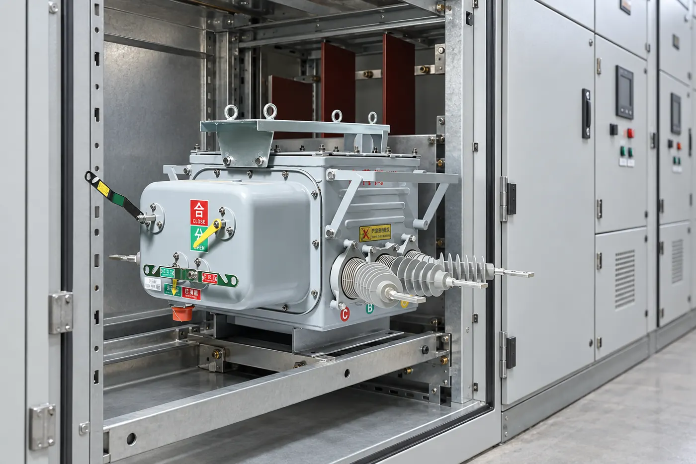
Lineup integration is an assembly decision. IEC 62271-200 addresses metal-enclosed switchgear above 1 kV through 52 kV, including partitions, interlocks, service continuity and internal-arc classification where specified. A compliant component does not automatically preserve assembly performance. Check bus connections, shutters, earthing, racking, control plugs, clearances and protection wiring.
Total cost needs the same boundary. A contactor price is incomplete without fuses, overload protection, spares and outage labor; a breaker price may exclude the relay, instrument transformers, adaptation and commissioning. For retrofits, consult the VCB mounting and retrofit configuration guide before treating footprint compatibility as electrical compatibility.
What evidence should procurement require for either device?
Use IEC 62271-106 for medium-voltage contactors/controllers, IEC 62271-100 for AC circuit-breakers and IEC 62271-200 for the metal-enclosed assembly. In North American breaker specifications, IEEE C37.04 defines rating structure and IEEE C37.09 covers test procedures. These documents define requirements and tests; citing one is not, by itself, proof that a particular configuration has been certified or tested.
Request type-test evidence applicable to the offered design, routine-test records for delivered equipment and an agreed site-acceptance plan. Site checks may include visual and mechanical inspection, interlocks, control logic, insulation resistance, main-circuit resistance where applicable, breaker timing, relay secondary injection and functional trip tests. The exact scope comes from the standard, manufacturer instructions and project risk assessment; the vacuum circuit breaker test guide provides additional commissioning context.
- Define the operating profile and protection objective before naming a device: load type, operations, starting duty, fault level and required clearing times.
- Build a one-line protection concept showing overload, short-circuit and earth-fault functions, plus which device interrupts each duty.
- Match the destination-market standard and edition, then request applicable type tests, routine tests, coordination data and deviations.
- Verify lineup interfaces and safety functions from drawings; repeat affected assembly and commissioning checks after a retrofit.
- Compare lifecycle scope, including fuses, relays, spares, scheduled tests, replacement labor and production downtime.
Fuerte supplies medium-voltage vacuum circuit breaker equipment and can be considered when a verified breaker solution fits the protection study. Buyers should send every candidate supplier the same duty schedule, lineup drawings, control requirements and evidence list; do not ask a breaker vendor to solve an undefined motor-control or coordination problem.
Часто задаваемые вопросы
What is the difference between a vacuum contactor unit and a vacuum circuit breaker?
A vacuum contactor is primarily designed for frequent operational switching of loads, while a вакуумный выключатель is designed to interrupt specified fault current as part of a protection scheme. Both use vacuum interrupters, but their ratings, mechanisms, standards and tested duties are not interchangeable.
Can a vacuum contactor replace a VCB for motor control?
It may perform the frequent start-stop function more appropriately, but it does not automatically replace the VCB’s short-circuit role. Use a contactor only with a verified overload and short-circuit protection package coordinated for the available fault current.
Which device provides short-circuit protection?
A correctly rated VCB can interrupt assigned short-circuit current when tripped by the protection system. A contactor-based controller commonly relies on coordinated current-limiting fuses or an upstream breaker; confirm the tested combination rather than assuming the contactor clears the fault.
How do VCB and vacuum contactor ratings differ?
VCB ratings emphasize making and breaking current, short-time withstand, operating sequence, dielectric duty and relay-controlled interruption. Contactor ratings emphasize controlled-load utilization, operational frequency and endurance, alongside the rating of the complete controller and its short-circuit protective device.
When is a vacuum contactor preferred?
It is often preferred when a motor or other defined load requires frequent controlled operations and a coordinated protection package is available. Verify starts per hour, utilization category, load transients, environmental conditions and fuse or breaker coordination.
Can both devices be used in the same switchgear lineup?
Yes, different feeders in one lineup can use contactor-based controllers and VCBs when the assembly design supports them. IEC 62271-200 considerations, bus ratings, partitions, interlocks, internal-arc classification, control schemes and protection selectivity must be verified for the actual lineup.
Ссылки
- IEC 62271-106, High-voltage switchgear and controlgear—Alternating-current contactors, contactor-based controllers and motor-starters.
- IEC 62271-100, High-voltage switchgear and controlgear—Alternating-current circuit-breakers.
- IEC 62271-200, AC metal-enclosed switchgear and controlgear.
- IEEE C37.04, Ratings and requirements for AC high-voltage circuit breakers.
- IEEE C37.09, Test procedures for AC high-voltage circuit breakers.
The right vacuum device is the one whose tested duty matches the load, fault study and complete switchgear—not the one whose name or outline looks closest. To review a breaker application, explore Fuerte’s medium-voltage vacuum circuit breaker information and contact the team with your single-line diagram, rating schedule, operating profile and lineup interfaces.