








Before installing or maintaining an overhead switch isolasi, confirm how the feeder will be de-energized and what the switch is rated to do. A visible open gap identifies an isolation point; it does not make a plain disconnector suitable for interrupting load or fault current. Check the approved switching sequence and nameplate before adjusting the blades, operating rod or contacts.
IEC 62271-102 covers AC disconnectors and earthing switches for installations above 1 kV. Match the device duty to the switching diagram, then survey the line, set the bracket and operating mechanism square, verify contact pressure, interlocking and earthing, and record the commissioning observations. Inspect at intervals defined by the utility or OEM, with additional condition checks when circumstances warrant them.
Confirm what the switch is allowed to interrupt
The visible blade gap is valuable because a crew can confirm that a section is separated, but the gap alone does not prove that the device can interrupt current. A pemutus daya is normally used after the circuit has been interrupted elsewhere. A load-break switch has a documented load-switching duty, while a circuit breaker, recloser or fuse is selected for fault interruption and coordinated protection. The approved single-line diagram and the manufacturer’s nameplate should decide which operation is permitted.
| Intended operation | What must be verified | Evidence before operation |
|---|---|---|
| Visible isolation | Disconnector duty, visible open position and mechanical travel | Nameplate, approved switching sequence and open-position inspection |
| Load switching | Explicit load-break rating and the utility’s operating procedure | Product data, applicable test evidence and scheme drawing |
| Gangguan kesalahan | Interrupting device and protection-coordination duty | Fault study, protection settings and the selected vacuum circuit breaker or fuse data |
| Earthing position, where provided | Interlock logic and the designed earthing path | Wiring or mechanism drawing and continuity record |
For a medium-voltage overhead application, the disconnector switch selection guide is a useful companion to the project’s own utility standard. It should support the decision, not replace a duty review for the actual feeder.
Survey the pole and align the mechanism
Start with the site rather than the catalogue. Record nominal system voltage, phase arrangement, conductor size and tension, pole or crossarm condition, available clearances, and the local utility’s switching convention. Add environmental observations such as coastal salt, industrial dust, altitude, ice or wind exposure where they affect the selected insulation, hardware or inspection plan. These are project inputs; they are not universal ratings that can be inferred from a generic isolating-switch photograph.
Set blade travel against the approved drawing
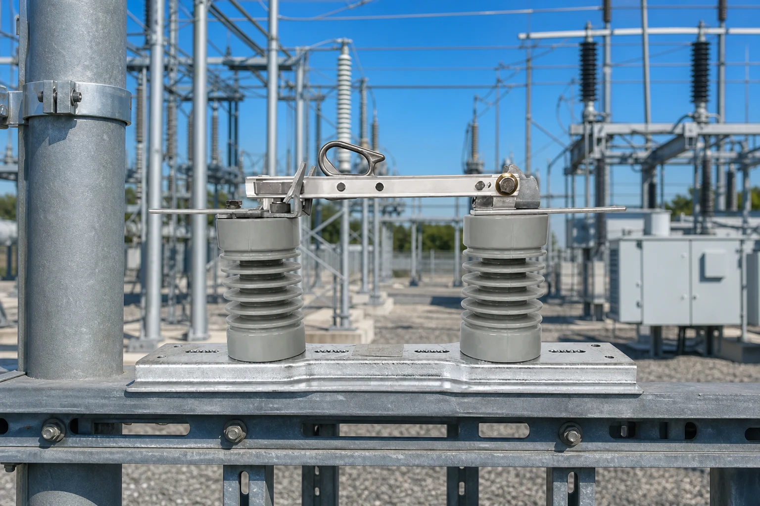
Before lifting the assembly, compare the pole hardware, phase spacing and conductor terminals with the approved drawing. Set the support square to the pole or crossarm, then move the blades through the complete travel by hand where the design permits. The closed position should bring the contacts together without side loading; the open position should provide the specified visible gap. Follow the manufacturer’s torque and adjustment values rather than substituting a remembered value from another model.
Check that the operating rod, bearings and handle reach their end stops without binding. Contact pressure is a mechanical condition to verify against the drawing or service instruction; it is not established merely because the handle reaches a locked position. If the line uses polymer supports, cross-check the polymer pin insulator selection guidance with the project’s insulation and pollution assumptions.
Test the designed interlocks and earthing path
An interlock should prevent the sequence that the scheme does not permit, such as confusing a visible isolating position with a load-break operation. Test padlocks, trapped-key features or electrical interlocks included in the design, and record the result. Where an earthing switch or bonding conductor is supplied, verify the designed connection and continuity using the utility’s specified method. Do not improvise an earthing arrangement from a nearby pole bond.
Record commissioning checks and plan inspections
Commissioning should leave a baseline that another crew can understand. With the circuit in the state required by the approved procedure, operate the switch through a complete open-close sequence and observe blade alignment, latching, linkage travel and the visible gap. Record serial or asset identification, as-built orientation, photographs and any adjustment made. If the utility or OEM calls for contact-resistance measurement, use the specified low-resistance ohmmeter method and retain the reading with the test conditions; do not invent an acceptance limit.
Periodic inspection is condition- and procedure-driven. Use the utility or OEM interval, then add a condition review after a storm, fault operation, major conductor work or a change in pollution exposure. Inspect contact surfaces, fasteners, bearings, insulator sheds, arcing components where fitted, and the operating rod. Clean only with approved materials, replace damaged parts with the documented equivalent, and update the as-built drawing after any mechanism change.
Treat the baseline as evidence, not as a promise of a fixed service interval. The utility procedure and the equipment instruction remain controlling documents.
Trace incomplete travel, heating and contamination
Environment changes the questions asked during inspection. Salt deposits and industrial dust can make the insulator surface more difficult to assess; repeated wetting can expose contamination paths; ice, wind or vibration can reveal a weak bracket or loose linkage. The correct response is to document the condition, compare it with the OEM’s cleaning or replacement instruction, and involve the utility engineer when the observed condition changes the switching sequence or clearance assumptions.
| Observed symptom | Cause to verify | Evidence-led action |
|---|---|---|
| Uneven visible gap or blade stops short | Bracket out of square, rod travel or phase geometry | Compare as-built measurements with the drawing; adjust only to the OEM procedure |
| Discoloration or abnormal heating at a joint | Loose connector, contamination or insufficient contact pressure | Use the utility’s approved thermal or contact-resistance check and inspect the joint when de-energized |
| Handle will not latch | Interlock, padlock, damaged stop or incomplete mechanism travel | Trace the designed sequence; do not force the handle or bypass the interlock |
| Tracking, chalking or cracked insulator surface | Contamination, moisture, impact or material damage | Photograph the condition, follow the approved cleaning or replacement instruction, and record the environment |
| Corrosion or fretting after coastal exposure | Environment-to-material mismatch or water retention at hardware | Check the specified hardware finish, drainage and replacement parts with the responsible engineer |
The useful diagnostic question is “what changed?” A repeatable mechanical symptom after a storm points to a different investigation than a high contact-resistance reading after a connector change. Keeping photographs, readings and work orders together makes that distinction visible to the next maintenance team.
Specify the duty and hand over usable records
- State the switching duty in the single-line diagram: visible isolation, load switching, earthing or fault interruption.
- Attach site inputs to the RFQ: system voltage, conductor and pole arrangement, clearances, environment and utility rules.
- Request the installation drawing, adjustment values, operating sequence and applicable test evidence before production release.
- Define the commissioning record: asset identity, open/close observations, interlock result, earthing verification and any specified measurements.
- Agree the inspection trigger with the utility or OEM, including storm, fault and pollution-condition reviews.
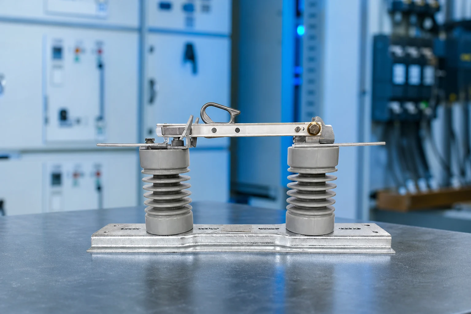
Fuerte’s isolating switch product range can be reviewed against these project inputs and the approved drawing. The product page is a starting point for configuration questions; it does not replace the local utility’s acceptance criteria.
Installation and operation questions
Are overhead isolating switches and disconnectors the same?
In many utility documents, “isolating switch” and “disconnector” describe the visible-isolation function. The exact permitted operation still comes from the nameplate, standard and approved switching procedure, so the terms should not be used to infer load-break or fault-interruption duty.
When may an isolating switch interrupt load current?
Only when the specific device is documented and approved for load-break duty. A plain disconnector is normally operated after current has been interrupted elsewhere; confirm the sequence with the utility or responsible engineer.
What details belong in a pre-installation survey?
Record system voltage, conductor and support geometry, clearances, hardware condition and environmental exposure. Include the utility’s switching convention and any site-specific insulation or earthing requirements before the equipment is released.
What should commissioning tests check?
Operate the mechanism through its approved sequence and check alignment, latching, visible opening, interlocks and the designed earthing path. If required by the utility or OEM, add a specified contact-resistance or insulation test and retain the method and conditions with the record.
When should an overhead isolating switch be inspected?
There is no universal interval that fits every line. Use the utility or OEM maintenance plan, and add condition checks after storms, fault operations, major line work or a change in pollution exposure.
Why might a switch stop short of fully opening or closing?
Common investigation points are a misaligned bracket, incorrect rod travel, a damaged stop, contamination or an interlock that has not completed its sequence. Compare the mechanism with the approved drawing and do not force or bypass it.
Keep isolation duty clear through the service life
An overhead isolating switch earns its place by making the intended isolation point unambiguous; it is not a substitute for a load-break switch or fault-interrupting breaker unless its documented duty says so. The reliable decision sequence is therefore: map the line and environment, confirm the switching duty and standard, install the support and operating mechanism square, verify contacts, interlocks and earthing, then record commissioning evidence. Periodic inspection should follow the utility or OEM plan and tighten after storms, faults or changed pollution exposure. A visible gap, contact condition and operating force are useful clues, but none removes the need to follow the approved switching procedure. Fuerte can help buyers compare project data with its isolating switch product range; close the choice with verified drawings and a documented acceptance check. Contact FUERTE engineering support with the line and duty details before procurement.