








A visible opening point, a load-switching capability and a fault-interruption rating describe different duties. An overhead switch isolasi should not be specified by catalogue name alone when the operating schedule expects one device to perform several of these jobs. The required function, network conditions, mechanical interfaces and interlock sequence need to be stated together before procurement. This guide explains how to define the duty, compare electrical and mechanical requirements, and plan installation and inspection. It also identifies the evidence needed to distinguish a product’s declared capability from the owner’s approval of the complete line arrangement.
Summary: Select a pemutus daya by its actual duty first: visible isolation is different from load breaking or fault interruption. Confirm maximum system voltage, continuous current, short-time withstand, insulation coordination, interlocking, earthing, environmental exposure, and the utility’s operating procedure before comparing quotations. IEC 62271-102:2018 covers alternating-current disconnectors and earthing switches; it does not turn every disconnector into a circuit breaker. Put the switching duty, site conditions, inspection evidence, and acceptance tests in the RFQ, then ask the supplier to show how each requirement is met.
Start With the Switching Duty, Not the Catalogue Name
A disconnector creates a defined open gap so an isolated line section can be identified before maintenance. A disconnect-only device is normally operated after the circuit is de-energized; a load-break version has a stated switching duty and an operating mechanism designed for that duty. Neither should be assumed to clear a short circuit. Fault interruption remains the job of a circuit breaker, fuse, recloser, or another protection device selected for the network study.
Write the intended sequence in the project documents: which upstream device opens, when the disconnector may move, how absence of voltage is verified, and when the earthing switch may close. If the line must be sectionalized while carrying load, specify load-break capability explicitly and request the applicable test evidence. For an isolation-only point, define the open-position indication and the lockable operating position instead of paying for an unneeded duty.
A practical isolating switch installation guide can help align the single-line diagram, field labels, and maintenance instructions. The link is useful during design review, but the utility switching rules and the approved method statement remain controlling documents.
Match Voltage, Current, and Withstand to the Network Study
Use the maximum system voltage, not only the nominal feeder label, when selecting the voltage class. Continuous current should be checked against the conductor ampacity, expected transfer or bypass current, and the temperature assumptions used in the design. Short-time and peak withstand must be compared with the prospective fault current at the pole; the correct value depends on the network source impedance and clearing time.
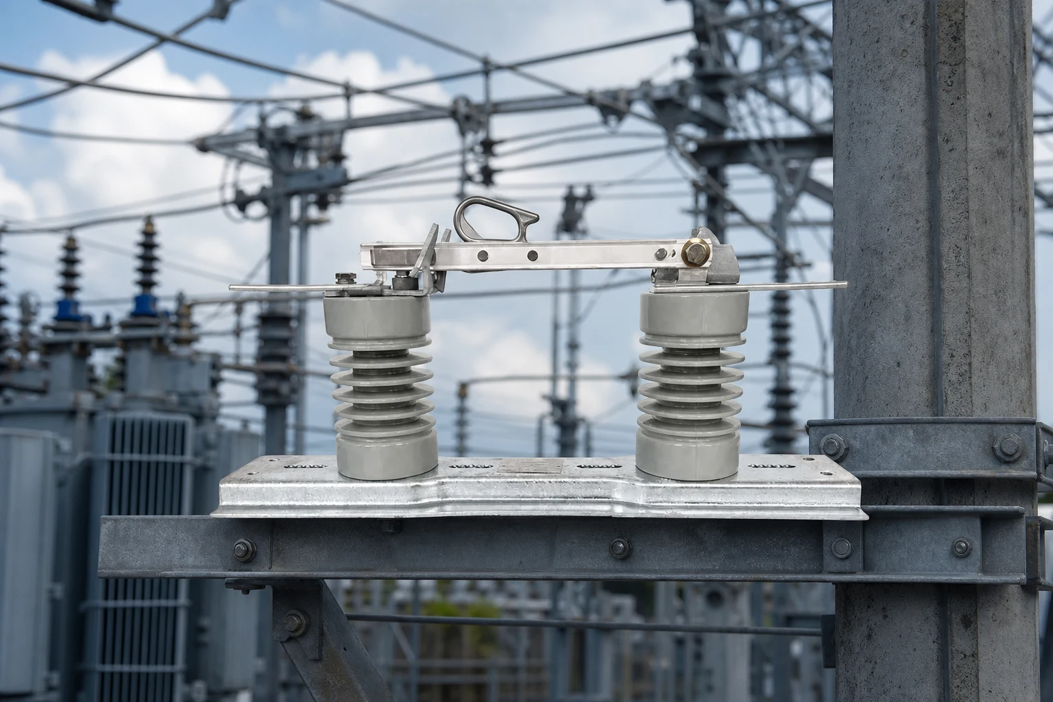
Insulation coordination also matters. Confirm power-frequency withstand, impulse withstand or BIL where the project specification uses that term, phase-to-phase clearances, and creepage for the site’s pollution and altitude conditions. A rating copied from a similar feeder can be wrong when the transformer arrangement, lightning exposure, or elevation changes.
| Selection item | Evidence to place in the RFQ | Why it changes the choice |
|---|---|---|
| Maximum system voltage | Utility voltage range and insulation-coordination study | Sets the voltage class, clearances, and dielectric test level |
| Continuous current | Load-flow result, conductor ampacity, and transfer scenario | Avoids heating or an undersized bypass path |
| Short-time and peak withstand | Fault-study current and protection clearing time | Separates a sectionalizing device from a fault interrupter |
| Operating duty | Load-break, no-load, or earthing-switch sequence | Determines mechanism, interlock, and test requirements |
Do not treat a nameplate current as a fault rating, and do not infer a load-break duty from a hook, handle, or arc horn shown in a photograph. Ask for the exact configuration covered by the supplier’s report, including insulators, operating shaft, mounting frame, and earthing accessories.
Check Interlocking, Earthing, and Outdoor Exposure
Mechanical interlocking should make the intended sequence obvious. A common arrangement prevents the earthing switch from closing while the line-side disconnector is closed, and prevents the disconnector from opening or closing when the earthing position would create an unintended connection. Confirm the actual key, padlock, or trapped-key logic in drawings; a label that says “interlocked” is not enough.
Earthing provisions must be coordinated with the utility’s portable-grounding practice and the pole’s earth conductor. Verify the earthing switch’s rated making or short-time duty when one is provided, the accessible operating point, and the clearance between live parts and the grounded frame. The specification should state whether the equipment includes an earthing switch or only a provision for site-installed grounds.
For outdoor lines, document solar exposure, rain, salt or industrial contamination, ice or wind loading where relevant, altitude, and the available mounting space. Review creepage, seals, corrosion protection, UV-exposed polymers, and drain paths as a system. These details affect inspection intervals and hardware selection; they do not justify a universal lifespan claim.
Where polymer insulation is being considered, compare the supplier’s stated creepage and material information with the site’s contamination class. A polymer-insulator product line can be a useful reference, but it should not be treated as proof that a particular disconnector assembly meets the project dielectric requirements.
Plan Installation, Inspection, and Failure-Mode Checks
Before shipment, approve the pole interface, phase spacing, conductor connection, operating-rod travel, and torque limits. At site, inspect alignment, fastener security, contact engagement, blade position indication, earth continuity, and clearances. Functional operation should be recorded in both open and closed positions; any load-break test or timing test should follow the specified equipment duty and available test method.
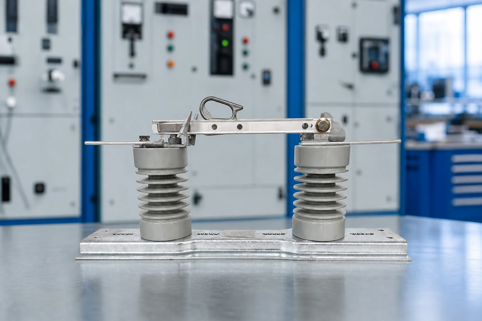
Common failure modes are selection-related: a disconnect-only device is operated under load; a short-time withstand value does not match the fault study; a bent operating rod leaves one phase partially engaged; contamination creates tracking on an exposed insulator; or a missing interlock allows an unsafe sequence. A good inspection record links the observation to a drawing revision, serial number, and corrective action.
| Failure mode | Early check | Procurement or field response |
|---|---|---|
| Operation under the wrong duty | Compare switching schedule with nameplate and manual | Specify load-break duty or revise the sequence |
| Incomplete blade engagement | Observe all phases through full travel | Correct alignment and verify position indication |
| Insulator tracking or flashover | Inspect after rain, pollution, or unusual discharge | Recheck creepage, washing plan, and site exposure |
| Interlock bypass or unclear earth state | Walk the key or padlock sequence with operators | Revise hardware, labels, or operating procedure |
Commissioning records should include the approved single-line diagram, torque or alignment notes where specified, contact and earth-continuity observations, photographs of the open position, and the final operating instructions. Periodic inspection should be based on utility practice, environment, operating frequency, and observed condition rather than a generic interval.
Use Standards and Evidence to Compare Quotations
IEC 62271-102:2018 sets requirements and tests for alternating-current disconnectors and earthing switches within the IEC 62271 high-voltage switchgear family. Its scope is the equipment and its declared duties; it is not a blanket product certification, and it does not replace local utility rules, insulation coordination, or protection studies. Ask which edition and clauses the quotation uses, then check that the tested arrangement matches the supplied pole-top configuration.
In markets using IEEE practice, identify the applicable C37 document in the project specification and keep the comparison fair: the same voltage class, current duty, short-time withstand, operating mechanism, and accessories. A supplier may provide a report from an independent laboratory, a routine test record, or a design declaration; these are different forms of evidence. Record exactly what was supplied and what remains a project acceptance test.
For adjacent protection choices, a fuse cutout selection guide and the vacuum circuit breaker options page can help separate isolation, protection, and interruption functions. Use those references to frame the system, then request a configuration-specific quotation from the manufacturer.
- Attach the single-line diagram, fault level, load current, environmental data, and operating sequence to the RFQ.
- Require a dimensioned drawing showing phase spacing, mounting, operating rod, interlocks, and earth connections.
- List the factory evidence, routine checks, site acceptance tests, manuals, spare parts, and drawing revisions included in the offer.
- Normalize delivery terms, commissioning support, replacement parts, and documentation before comparing total installed cost.
FUERTE can be included at the technical-clarification stage when a buyer needs a configurable isolating-switch arrangement, drawing review, or export documentation. Use the project parameters rather than a generic catalogue number when requesting a response.
Pertanyaan yang Sering Diajukan
What is a disconnector switch used for on an overhead line?
It provides a visible isolation point for a line section or connected apparatus. Whether it may be operated under load depends on its declared duty and the utility’s switching procedure, so confirm both before operation.
Can a disconnector interrupt a short circuit?
A standard disconnect-only device is not a fault interrupter. Fault clearing must be assigned to a correctly coordinated breaker, fuse, recloser, or other protection device; select a disconnector’s short-time withstand from the fault study.
Which ratings should appear on the RFQ?
State maximum system voltage, continuous current, short-time and peak withstand, insulation withstand, operating duty, and environmental conditions. Include the source study or utility requirement so suppliers do not fill gaps with generic catalogue values.
When is an earthing switch required?
That depends on the approved isolation and grounding procedure. If an earthing switch is included, confirm its interlock, accessible operating position, making or short-time duty, and coordination with portable protective grounds.
What should be checked during site inspection?
Check mounting and phase clearances, blade alignment, full mechanical travel, position indication, earth continuity, interlocks, labels, and condition of exposed insulation. Record the results against the approved drawings and the supplier’s commissioning instructions.
Kesimpulan
A medium-voltage overhead-line disconnector is selected correctly when its visible isolation function, switching duty, withstand requirements, and operating sequence agree on the same drawing. Start with the utility procedure and fault study; then confirm voltage, current, insulation coordination, interlocking, earthing, and outdoor exposure. At procurement, require configuration-specific evidence and define the site checks that will accept the equipment. During operation, treat position indication and inspection records as part of the engineered system, not as paperwork added after delivery. The useful question is not “Which switch has the highest catalogue rating?” but “Which declared duty matches this line, this environment, and this sequence?” For a project review, see the FUERTE isolating-switch range and contact the team with your single-line diagram, fault level, and mounting requirements.