








A pemutus sirkuit vakum‘s opening indication is only one part of its operating sequence. The protection relay must issue a valid trip, the mechanism must separate the contacts as specified, and the interrupter must withstand the recovery voltage after current zero. A mismatch in contact travel, control voltage or operating duty can prevent that sequence from meeting the installation requirements even when the vacuum bottle itself appears intact. Understanding the principle therefore means following the relay, mechanism and interrupter together. This guide explains their roles, the difference between interrupting and insulating functions, and the records needed to check a proposed medium-voltage breaker.
Summary: A vacuum circuit breaker (VCB) interrupts an AC fault by separating contacts inside a sealed vakum interrupter and allowing the arc to die at the natural current zero. In a 50 Hz system, current reaches that zero 100 times per second; the interrupter must then recover dielectric strength quickly enough to withstand transient recovery voltage. IEC 62271-100:2021 provides the high-voltage AC circuit-breaker framework for making, breaking, dielectric and mechanical duties. Specify the short-circuit rating, operating sequence, contact-travel data and applicable tests together—do not choose a VCB from voltage alone.
Bagaimana cara kerja pemutus sirkuit vakum?
A VCB uses a sealed vacuum interrupter as the switching chamber. Its fixed and moving contacts carry load current when closed. When a protection relay detects an abnormal current, an operating drive pulls the moving contact away from the fixed contact. A short metal-vapour arc forms between the separating contacts, but the chamber contains no air or oil to sustain a conventional arc column.
The arc is therefore governed by contact material, contact speed, electrode geometry and the AC waveform. As the alternating current approaches its natural zero, the metal vapour condenses on the contacts and shield surfaces. If the contact gap and dielectric recovery are adequate at that instant, the arc does not re-strike; the open interrupter then withstands the transient recovery voltage imposed by the network.
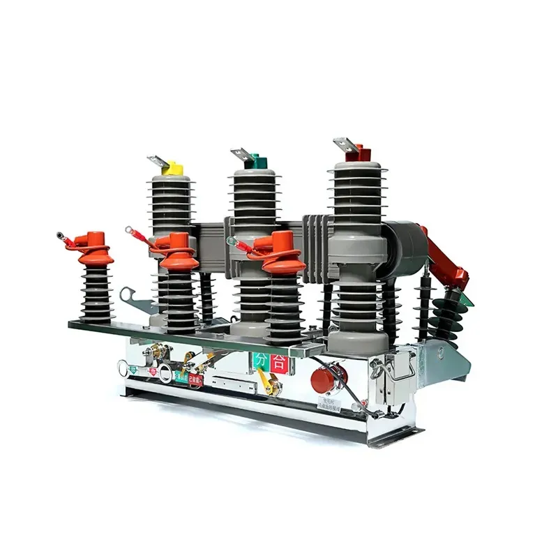
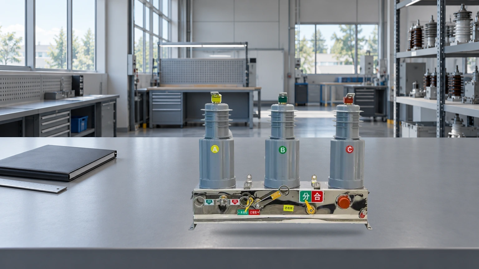
This is why a vacuum circuit breaker is a coordinated system rather than a vacuum bottle by itself. The interrupter, drive, linkage, insulation and control circuit must all meet the duty shown on the nameplate and the project single-line diagram.
From trip signal to arc extinction: the operating sequence
- Fault recognition. A protection relay or release compares measured current and voltage with its configured thresholds. It sends a trip signal to the breaker’s trip coil; the relay settings and clearing time remain part of the protection study.
- Drive release. The trip coil unlatches a charged spring, motor-spring, hydraulic or other approved operating mechanism. The drive supplies the force and timing; it does not extinguish the arc itself.
- Contact travel. A linkage and operating rod translate the drive motion into the moving contact. Opening speed, contact wipe and final gap must remain within the interrupter manufacturer’s tolerances. Too little travel can leave an unsafe gap; excessive impact can increase mechanical stress.
- Arc formation. As the contacts part, current continues briefly through a metal-vapour arc. The interrupter’s contact shape and shield manage the vapour and electric field while the contacts continue moving.
- Current-zero interruption. At the next natural AC current zero, the plasma loses its source. In a 50 Hz circuit this opportunity occurs every 10 ms, although the actual interruption depends on the circuit, contact material and recovery voltage.
- Dielectric recovery. Vapour condenses and the gap regains insulation strength. The interrupter must withstand transient recovery voltage without restriking. The mechanism completes its open stroke, and auxiliary contacts report the open state to the control and interlocking circuits.
The sequence explains why a fast trip command alone does not guarantee interruption. Protection timing, drive energy, contact travel, interrupter rating and system transients must be compatible.
Roles of the interrupter, contacts, travel and drive
Itu vakum interrupter is the sealed pressure vessel that contains the contacts, shields and insulating envelope. It provides the controlled arc environment and the post-current-zero dielectric path. A vacuum-tight ceramic or glass assembly is not a substitute for a verified type and production test record.
The contacts carry current in the closed position and shape the arc during opening. Their material and profile influence chopping current, welding tendency and dielectric recovery. The moving contact must follow a defined travel curve: initial separation, arcing travel, overtravel or wipe, and final open gap are mechanical values to be measured, not estimated by appearance.
The drive stores and releases energy, while the linkage transfers that energy to one or three poles. Closing and opening times, pole simultaneity, anti-pumping logic and the auxiliary-contact state are practical commissioning checks. If the operating mechanism is misadjusted, a correctly rated interrupter can still fail to meet its specified duty.
VCB compared with air and SF6 circuit breakers
The appropriate comparison is about interruption physics, verification and installed-system requirements—not a universal “best” technology. The table below uses neutral tendencies; actual maintenance and cost depend on rating, duty, enclosure, environment and local service capability.
| Dimensi keputusan | Pemutus sirkuit vakum | Air circuit breaker | Pemutus sirkuit SF6 |
|---|---|---|---|
| Arc medium | Sealed vacuum interrupter | Air in an arc chamber | SF6 gas in a sealed or monitored enclosure |
| Interruption event | Metal-vapour arc extinguishes at AC current zero; dielectric recovery follows | Arc is lengthened, cooled and divided in air | Gas flow and dielectric properties control the arc |
| Routine service focus | Mechanism lubrication, contact travel, insulation and interrupter integrity checks | Arc chutes, contacts, mechanism and insulation | Gas density or pressure, leakage controls, mechanism and insulation |
| Installation considerations | Commonly selected for distribution and industrial medium-voltage assemblies; verify rating and application | Often used where accessible air arc-chute service and low-voltage architecture are appropriate | Selected where its voltage, current and switching duties justify a gas-insulated design |
| Bukti yang diminta | IEC 62271-100 test evidence, routine-test record and travel/time data | Applicable low-voltage or high-voltage test evidence and arc-chute data | Applicable type/routine tests plus gas-handling and leakage documentation |
Applications and sizing checks
VCBs are used in utility and industrial distribution, transformer feeders, motor control line-ups, renewable-energy collector systems and transport or infrastructure substations. The application does not determine the breaker in isolation; fault level, switching duty, grounding, altitude, ambient conditions and the upstream/downstream protection sequence all matter.
| Application question | Check before ordering | Mengapa hal ini penting |
|---|---|---|
| What circuit is being protected? | Nominal voltage, frequency, continuous current and system grounding | Confirms the basic electrical duty and insulation coordination |
| What fault must it interrupt? | Available short-circuit current, X/R ratio, making current and required operating sequence | Links the nameplate ratings to the network study rather than a generic catalogue value |
| How often will it operate? | Open-close and close-open-close sequences, motor/inrush duty and interlocks | Determines mechanism endurance and control-circuit requirements |
| What is the environment? | Altitude correction, temperature, humidity, pollution, seismic and enclosure conditions | Can change insulation, cooling, clearances and enclosure selection |
| How will it be verified? | Routine-test reports, dimensional/travel records, wiring diagrams and service access | Provides evidence for commissioning, maintenance and future troubleshooting |
IEC 62271-100:2021 and compliance context
IEC 62271-100:2021 is the international product standard for high-voltage alternating-current circuit-breakers. It sets the framework for rated characteristics and type-test duties such as dielectric tests, temperature-rise tests, short-circuit making and breaking, mechanical operation and verification of the interruption capability. It is a product standard and test framework—not a blanket certificate that every VCB is compliant.
Project documents should also identify the edition adopted by the destination market, the applicable general requirements in the IEC 62271 series, and any utility, grid-code or national deviations. Ask the supplier to map the offered model and configuration to the required rated voltage, frequency, normal current, short-circuit current, operating sequence, insulation level and environmental class. Unsupported claims about certification, emissions, service life or performance can create procurement disputes and leave the owner without evidence at acceptance.
How to select and procure a VCB
- Start with the single-line diagram and protection study; record prospective short-circuit current, clearing time and required switching sequence.
- Match the nameplate ratings and insulation level to the network, including altitude, ambient temperature and pollution assumptions.
- Request a dimensional drawing, control schematic, contact-travel/time limits and routine-test format before approving the purchase order.
- Define commissioning checks for pole simultaneity, opening/closing time, travel, interlocks, auxiliary contacts and insulation resistance, using the project procedure and manufacturer’s limits.
- Choose a supplier that can provide configuration support and traceable test documentation. For a configurable catalogue starting point, review medium-voltage vacuum circuit breakers and confirm the exact model against your duty schedule.
FAQs
How does a vacuum circuit breaker extinguish an arc?
The contacts separate inside a sealed vacuum interrupter, creating a short metal-vapour arc. When the AC current reaches its natural zero, the vapour condenses and the gap regains dielectric strength; the interrupter must then withstand transient recovery voltage without restriking.
What happens after a protection relay sends a trip signal?
The signal energizes the trip coil, releases the operating mechanism and drives the moving contact through its specified opening travel. The breaker is not considered fully open until the mechanism reaches its final position and the auxiliary/interlocking circuits confirm the state.
What voltage levels are vacuum circuit breakers suitable for?
Many distribution VCBs are supplied for medium-voltage systems, but the acceptable range is model-specific. Check the rated voltage, insulation level, short-circuit duty and the edition of the applicable IEC or national standard rather than assuming a generic 1–38 kV range.
What maintenance does a vacuum circuit breaker require?
Maintenance normally focuses on mechanism condition, lubrication, contact travel and timing, insulation, control wiring and interrupter integrity in accordance with the manufacturer and site procedure. The interval should follow operating duty and inspection evidence; it should not be inferred from a universal service-life number.
How should a buyer compare a VCB with an SF6 or air breaker?
Compare the complete duty: interruption medium, rated and short-circuit current, switching sequence, insulation coordination, enclosure, service capability and required documentation. A technology choice is sound only when its verified ratings and maintenance process fit the network and destination-market requirements.
Kesimpulan
A vacuum circuit breaker works because several timed events meet at one point: the protection system issues a valid trip, the drive releases enough energy, the linkage produces the specified contact travel, and the interrupter recovers insulation at the AC current zero. The vacuum is important, but it is not a stand-alone guarantee of interruption. IEC 62271-100:2021 gives buyers a common language for rated duties and test evidence; the project still has to define fault current, operating sequence, environment and commissioning checks. The practical lesson is simple: specify the system duty first, then verify the interrupter, mechanism and documentation as one assembly. CNFuerte can help you compare configurations and required records; review the product range and contact the team with your single-line diagram and rating schedule. In breaker selection, evidence and coordination matter more than a slogan.