
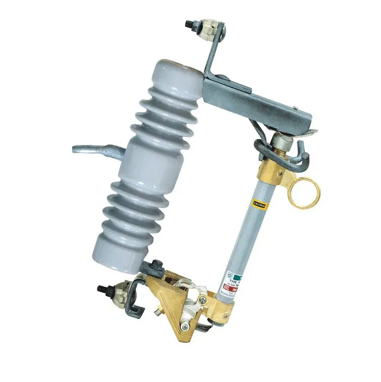
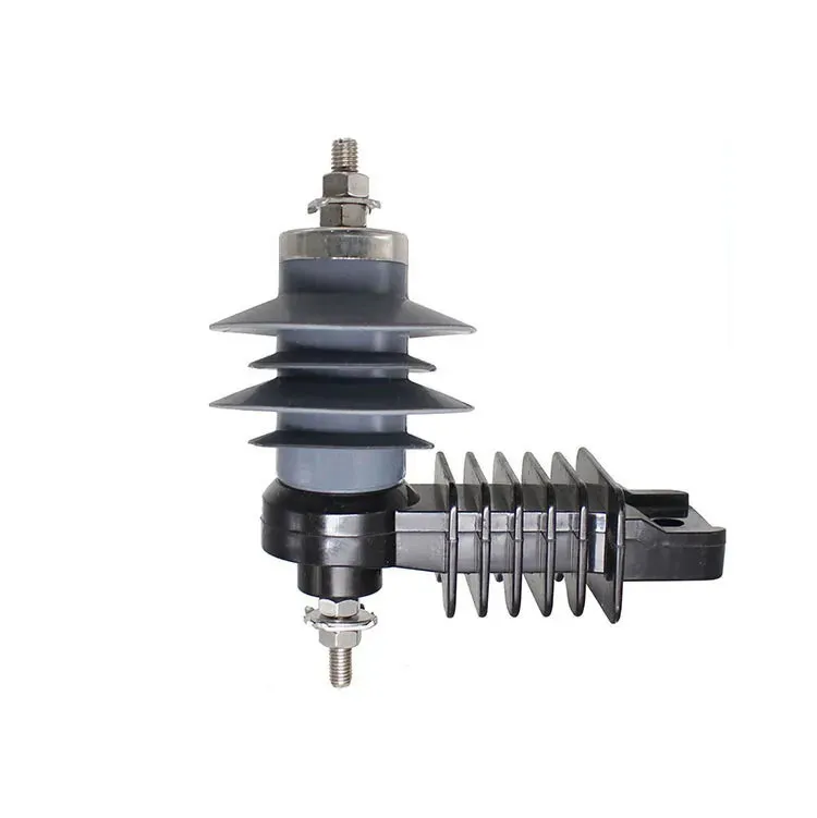
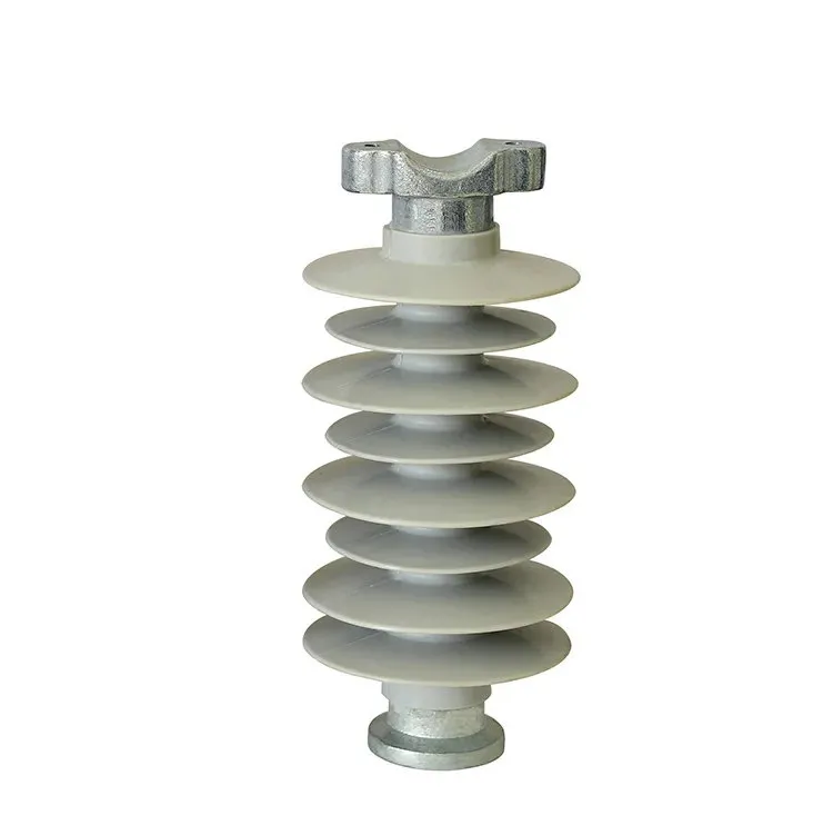
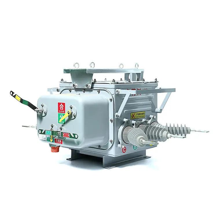
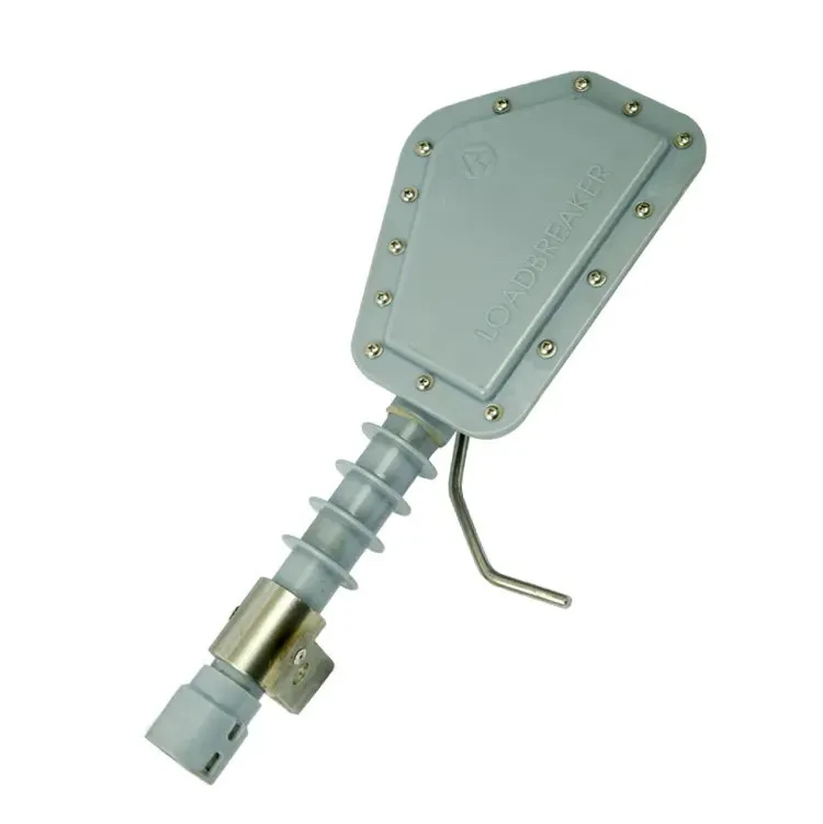


An empty area beside an operating substation can look like space for another circuit, but physical space is only one part of a bay extension. The existing busbar, fault duty, protection, isolation arrangements and maintenance access may all constrain what can be added. A layout that fits on a drawing may still require unacceptable outages or leave too little room to service equipment. Understanding a switchyard therefore means looking beyond rows of apparatus. The useful questions concern how a circuit connects, how it can be isolated, and what the operating team needs to keep the rest of the station available.
An electrical switchyard is the area containing switching equipment, busbars and associated circuit connections. It may form part of a larger substation. A bay is a functional grouping associated with a circuit, such as a line or transformer connection, rather than simply a marked rectangle or unused patch of land. Busbar arrangement and isolation provisions determine how that circuit interacts with the station. Access and working space must satisfy the applicable project and regulatory requirements. Before adding a bay, review the electrical studies and operating arrangement alongside the physical layout.
How is a switchyard different from a substation?
A substation can include switching areas, power transformers, control buildings and auxiliary facilities. ‘Switchyard’ usually refers to the switching area itself. A station used mainly for switching may have no power transformer. The electrical substation reference discusses this distinction between switching and transformation.
For a broader explanation, the electrical substation guide describes the facility’s role in the grid. In a layout review, use the project’s definitions and equipment designations so that civil, electrical and operating teams mean the same thing by a ‘bay’ or ‘switching area’.
What is a bay, and what does an open bay mean?
A bay groups the equipment and connections serving a particular circuit. Its contents depend on the single-line arrangement and operating duties. A line bay, transformer bay and bus-coupler bay serve different purposes; their physical appearance alone does not identify their function.
The phrase ‘open bays at a substation’ is ambiguous. It might refer to outdoor air-insulated construction, a spare position or a circuit whose switching equipment is open. Those meanings have different implications. A spare position is not necessarily equipped, and an open device does not by itself prove that a work area is safely isolated.
| Bay description | Function to establish | Question before a change |
|---|---|---|
| Line bay | Connect a line to the station arrangement | What line, protection and switching duties apply? |
| Transformer bay | Connect a transformer circuit | How does its protection and isolation interact with the transformer? |
| Bus-coupler or sectionalizing bay | Connect or separate bus sections as designed | Which operating states are permitted? |
| Spare bay position | Reserve a defined expansion opportunity | Which electrical and civil provisions already exist? |
What does the busbar arrangement determine?
Busbar arrangements influence circuit availability, maintenance options and the effect of a bus fault. More equipment can provide additional operating options, but also brings cost, space and protection complexity. There is no universally best arrangement independent of network needs.
Begin with the required service continuity and credible outage conditions. Then test how each proposed arrangement behaves during maintenance, equipment unavailability and faults. A general arrangement drawing shows where equipment sits; it does not replace the operating analysis or single-line diagram.
How does isolation affect a bay layout?
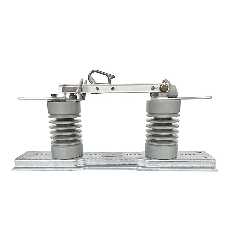
The layout must support the isolation arrangements defined by the design and site procedures. A breaker and a disconnector have different duties. The disconnector isolation function should be specified without assuming that the device can interrupt every current it may carry.
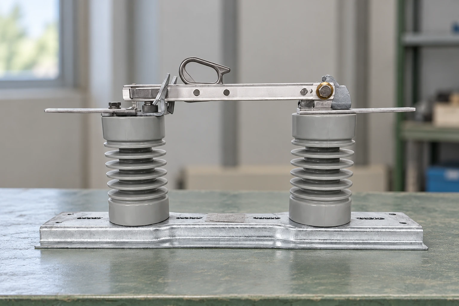
The reference switch illustrates a visible external mechanism, not a verified isolation state. A blade position in an illustration cannot prove that an installation is de-energized, protected against re-energization or safe to approach. Those conclusions require the responsible site’s procedures and verification.
US electric-power work requirements in 29 CFR 1910.269 address worker qualification, approach and de-energization conditions. They are a defined regulatory context rather than a generic switching sequence. A blog should not substitute an improvised operational procedure for an approved one.
What should be checked before adding another bay?
| Review area | Required check | Why an empty footprint is insufficient |
|---|---|---|
| System study | Load, fault conditions and intended circuit duty | A new connection can change existing equipment duties |
| Busbar and protection | Connection arrangement, ratings and protection changes | Spare physical space does not provide an electrical interface |
| Isolation and outages | Work boundaries and approved construction sequence | Installation may affect circuits that must remain available |
| Civil and access | Foundations, drainage, equipment access and maintenance routes | Equipment must be installed and serviced, not merely fitted |
| Control and auxiliary systems | Signals, wiring routes, supplies and document revisions | A new primary circuit needs supporting interfaces |
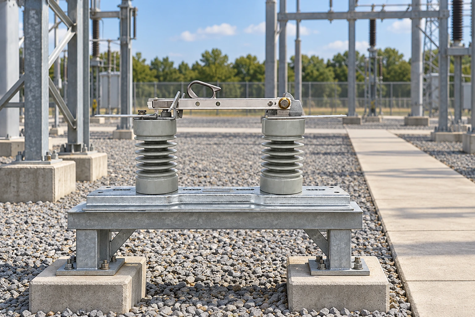
29 CFR 1910.303 includes access and working-space requirements for US workplace electrical installations. Do not lift a clearance from a table for a different voltage or installation and apply it to an entire switchyard. The project must identify the applicable provisions and design criteria.
A controlled drawing revision is also essential when existing equipment changes. Record which interfaces are retained, which are modified and which require confirmation from the equipment supplier. This is more useful than a layout labelled simply ‘future bay’ without defined provisions.
Foire aux questions
What is an electrical switchyard?
It is the area containing switching equipment, busbars and associated circuit connections. Its exact boundaries and terminology depend on the facility and project documentation.
How is a switchyard different from a substation?
A switchyard can be part of a substation, which may also include transformers, control buildings and auxiliary systems. A switching-only station may have no power transformer.
What is a bay in a switchyard?
A bay is a functional grouping of equipment and connections associated with a circuit or station function. It is not simply an equipment footprint or unused area.
How are incoming and outgoing circuits arranged?
They connect through the station’s approved busbar and switching arrangement. The single-line diagram defines the electrical relationships, while the layout determines how those relationships are physically implemented.
What does a busbar arrangement determine?
It influences operating options, circuit availability, maintenance and the consequences of faults. Selection must balance those requirements with space, cost and protection complexity.
Why are access and maintenance spaces important?
Equipment must be reachable for inspection, maintenance and replacement under the applicable safety arrangements. A layout that fits the initial equipment can still be unsuitable if access or future removal routes are missing.
How does equipment isolation affect bay design?
The bay must support the defined isolation and work arrangements, including their physical interfaces and operating constraints. A visible open device alone does not establish a safe work condition.
What should be checked before adding a new switchyard bay?
Review the system studies, existing equipment duties, busbar and protection arrangement, outage requirements, foundations, access, auxiliary systems and document revisions. Confirm what the reserved position actually includes.
Références
Sources vérifiées le 2 novembre 2026.
- Wikipedia — Sous-station électrique : fonctions et conception
- 29 CFR 1910.269 — Electric power generation, transmission and distribution (Cornell LII)
- 29 CFR 1910.303 — Exigences relatives aux installations électriques (Cornell LII)
Résumé
A switchyard bay is a working part of an electrical system, not just a location for equipment. Define the circuit’s role and busbar connection first, then review the protection, isolation and operating arrangements that make it usable. Only after those decisions are clear should the layout be judged for foundations, access and expansion. Empty land cannot demonstrate spare electrical capacity or a safe construction sequence. Keep the studies and drawings aligned with the equipment actually being supplied. Fuerte’s Interrupteurs isolés can be considered for the defined isolation function, with model-specific duties and mounting information checked against the project rather than inferred from a generic switchyard image.