








When a utility engineer reviews a failed transformer after a storm, the visible damage can suggest a poor arrester. The more useful question is whether the arrester was selected for the system’s continuous operating voltage, temporary overvoltage, discharge duty and installation geometry. A distribution arrester chosen only by nominal line voltage may leave excessive residual voltage at transformer terminals; an arrester with an unsuitable earth connection can also lose practical effectiveness. This guide gives a standards-based path for selecting a surge arrester in a transformer installation, substation or overhead line, then checking that the installed protection zone matches the design.
Resumen: Select the arrester from system data, not from the voltage printed on a catalogue page. Confirm the highest system voltage, grounding and fault-clearing conditions, then verify continuous operating voltage (Uc), rated voltage (Ur), temporary overvoltage withstand, nominal discharge current, line-discharge class where applicable, and protective level against the equipment insulation level. IEC 60099-4:2014+A1:2016 defines test requirements for metal-oxide surge arresters with or without gaps; it does not replace the utility’s network rules. Install the shortest practical connection to the protected terminals, route the earth lead directly, and document checks before energisation.
What does a surge arrester protect in each application?
A metal-oxide surge arrester limits transient overvoltages by conducting surge current to earth and returning to a high-resistance state at normal system voltage. The same principle applies across applications, but the exposure and required evidence differ.
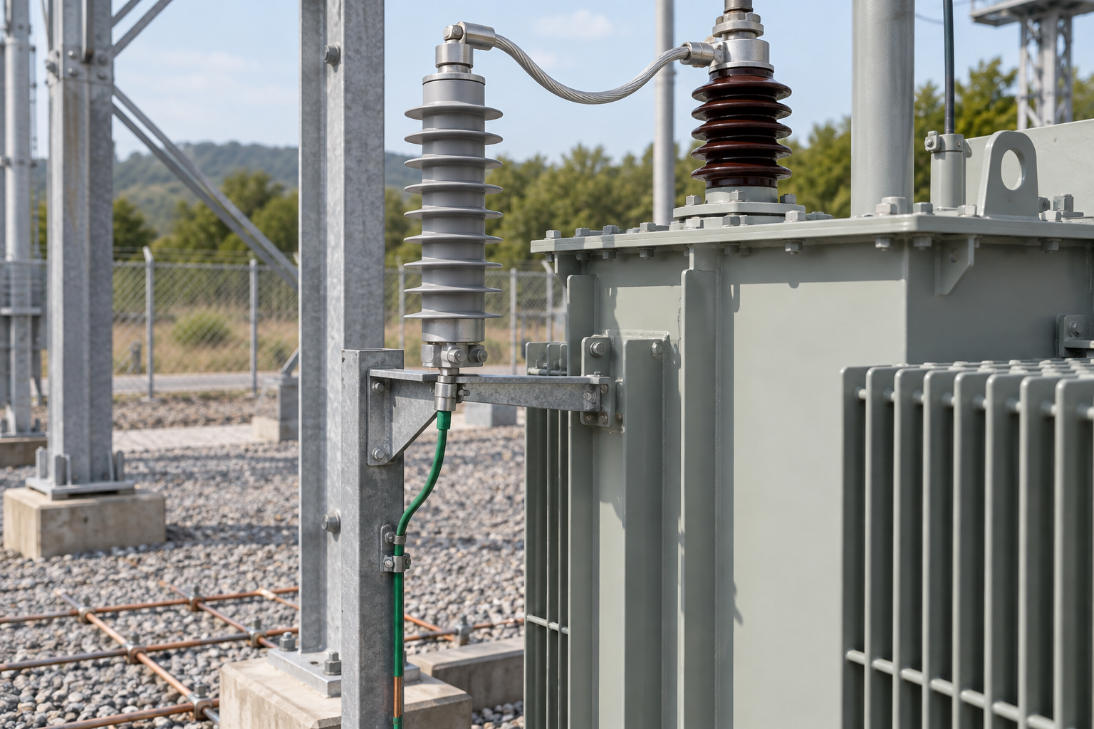
- At a transformer: the arrester protects winding insulation from lightning and switching surges. The arrester’s residual voltage, lead inductance and distance from the bushing are as important as its catalogue rating.
- In a substation: arresters coordinate protection for transformers, bus sections, cable terminations and line entrances. Switching duty and energy absorption can be more demanding than a simple service drop.
- On a distribution line: a distribution lightning arrester is exposed to direct and induced lightning, line faults and possible temporary overvoltage. Pole-top hardware, line configuration and grounding quality affect the protected zone.
The terms “transformer lightning arrester,” “distribution arrester,” and “power line lightning arrester” describe application context; they do not by themselves establish a rating. The design authority must map the application to network parameters and the applicable utility or IEEE practice.
How do you calculate a surge arrester rating?
Start with the highest continuous phase-to-earth voltage that the arrester can experience. For a grounded three-phase system, a preliminary check often relates phase-to-phase voltage to phase-to-earth voltage, but the final Uc choice must account for grounding coefficient, operating tolerances and the utility’s specified maximum voltage. Do not infer Uc from nominal 11 kV, 22 kV or 33 kV alone.
Next, determine the temporary overvoltage (TOV) envelope: its amplitude, duration and source. Earth faults, load rejection, ferroresonance and neutral displacement can produce different TOV conditions. Compare the network envelope with the arrester’s published TOV withstand curve and confirm that protective level at the equipment remains below the insulation coordination limit in IEC 60071-1 and the project insulation-coordination study.
Then select discharge and energy capability. Nominal discharge current is a standardized test current, commonly specified as 5 kA or 10 kA for distribution and station-class families, but the correct value depends on lightning exposure and network practice. Line-discharge class and switching-energy tests are relevant when the arrester must absorb repeated or high-energy events; they should be selected from the manufacturer’s IEC 60099-4 test data and the utility specification rather than guessed from the system voltage.
Which data must be on the selection worksheet?
| Input | Why it matters | Verification source |
|---|---|---|
| Highest system voltage and frequency | Sets the voltage stress used to establish Uc and Ur. | Network design and utility data sheet |
| Grounding method and earth-fault clearing time | Controls neutral displacement and TOV duration. | Protection study and grounding design |
| Equipment insulation level | Provides the coordination target for residual voltage. | IEC 60071 insulation-coordination study |
| Lightning exposure and line geometry | Influences discharge current, energy and arrester spacing. | Utility lightning and line-design criteria |
| Expected switching events | Can dominate energy duty in cable, capacitor or reactor circuits. | Switching-surge assessment and IEEE guidance |
How do line and substation arresters define protected zones?
A surge arrester protects a zone whose size depends on the surge front, conductor geometry, equipment insulation and the arrester’s distance. The farther a transformer terminal is from the arrester, the more lead inductance adds to the voltage during a fast front. For this reason, a lightning arrester 11kV line installation may need arresters at line entrances, riser poles or transformer bushings rather than one device at a remote switching point.
Substation layouts also require coordination between line entrance arresters and transformer arresters. A station-class device may offer greater energy capability, while a line arrester may be optimized for compact pole-top installation. The protected-zone decision should be documented on the single-line diagram, with arrester location, lead route, earth grid connection and equipment insulation level shown together.
How close should a surge arrester be installed to transformer terminals?
Install the arrester as close as practicable to the transformer bushing or cable termination, using short, straight conductors and avoiding loops. There is no universal distance in metres because the permissible separation depends on the surge rise time, conductor inductance, equipment BIL or rated insulation level, and the arrester’s residual-voltage characteristics. The engineering check should calculate or conservatively assess the voltage added by the connecting leads.
Keep phase and earth leads separated from unrelated control wiring, maintain mechanical support, and follow the manufacturer’s clearances. A neat-looking installation can still be electrically long if the lead runs around a cabinet or through a large loop.
How should grounding leads be routed and verified?
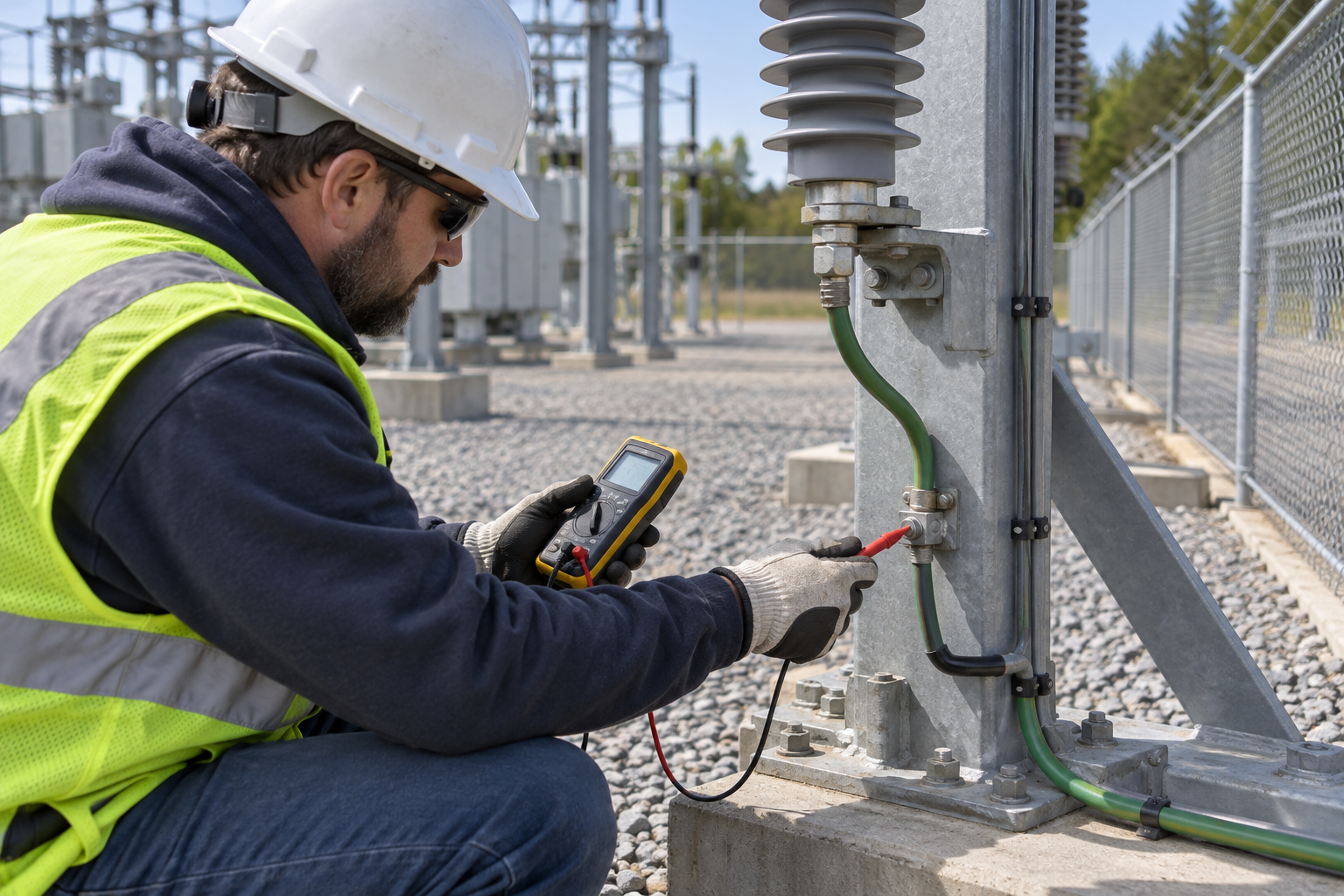
Route the earth lead directly to the designated earth grid, pole ground or transformer tank connection, with minimum length and bends consistent with mechanical safety. Verify continuity, connection tightness, corrosion protection and the design’s earth impedance or resistance criterion. A ground resistance number alone does not prove low inductive impedance during a lightning front; the route and bonding arrangement must also be inspected.
How do arrester types compare for transformers, substations and lines?
| Aplicación | Primary duty | Selection emphasis | Installation check |
|---|---|---|---|
| Transformer terminal arrester | Limit lightning and switching voltage at winding insulation | Uc/Ur, residual voltage, TOV and very short leads | Phase-to-bushing and direct earth connection |
| Substation line entrance arrester | Absorb incoming line surge energy and coordinate station insulation | Energy duty, discharge class, switching surges and grid bonding | Single-line location and earth-grid route |
| Distribution line arrester | Reduce flashover and induced-surge stress on overhead equipment | Exposure, mounting, line configuration, Uc and TOV | Pole hardware, phase spacing and ground continuity |
| Cable or GIS termination arrester | Control steep-front cable and switching transients | Residual voltage, frequency of events and enclosure coordination | Short termination leads and bonded screens/enclosure |
Which IEC and IEEE guidance should a buyer require?
IEC 60099-4 specifies metal-oxide surge arrester characteristics, routine tests, type tests and acceptance-related test methods for relevant designs. IEC 60071-1 provides the insulation-coordination framework used to compare protective levels with equipment insulation. IEEE Std C62.11 covers metal-oxide surge arresters for AC power circuits and is commonly used alongside utility-specific IEEE application guides. These documents define engineering and test expectations; they are not a blanket certification for every voltage class or installation.
Procurement documents should name the edition, test reports, routine-test records and environmental assumptions. Claims such as “IEC certified” should be supported by the exact product scope and independent evidence; a standard reference alone does not prove compliance with a purchaser’s complete specification.
What should buyers verify before ordering a line surge arrester?
- Issue a completed system-data sheet covering maximum voltage, grounding, fault duration, lightning exposure and insulation level.
- Compare Uc, Ur, TOV withstand, residual-voltage curves, nominal discharge current and energy or line-discharge class with the study.
- Request IEC 60099-4 test evidence, routine-test scope, dimensional drawings, terminal details and installation instructions.
- Review the physical arrangement: clearances, creepage, mounting strength, lead length, earth bonding and maintenance access.
- Record commissioning checks and define inspection triggers after major faults, lightning events or earth-grid work.
Fuerte can be considered at this stage when a project needs a configurable surge-arrester supply supported by drawings and technical documentation. Buyers can compare the technical evidence with the requirements for their own network, then review the site’s metal-oxide arrester selection guide and power-grid lightning arrester overview. The broader other-products catalogue is useful when the arrester must be coordinated with adjacent medium-voltage hardware.
What questions do engineers ask about surge arresters?
How do you calculate a surge arrester rating?
Establish Uc from the highest continuous phase-to-earth voltage, then check Ur, TOV withstand, residual voltage, discharge current and energy against the system study. The result must also coordinate with equipment insulation under IEC 60071; nominal line voltage alone is insufficient.
What is the purpose of a surge arrester in transformers?
It diverts lightning and switching surge current to earth so the voltage stress at transformer insulation stays within the coordinated protection level. Its value depends on correct rating, lead length, grounding and location beside the protected terminal.
What is a surge arrester in a substation?
It is a metal-oxide protective device installed at locations such as line entrances, transformer terminals or bus-connected equipment. Substation selection normally considers higher switching and energy duty, station insulation coordination and the earth-grid arrangement.
Are surge arresters grounded?
Yes. The arrester conducts surge current through its earth connection, so the phase and earth paths must be short, secure and bonded to the designed grounding system. Ground continuity and routing should be verified during commissioning.
What IEC standard applies to surge arresters?
IEC 60099-4 is the principal product standard for relevant metal-oxide surge arresters. IEC 60071-1 supports insulation coordination, while local utility rules and applicable IEEE documents may add application requirements.
What is the line-discharge class of a surge arrester?
Line-discharge class is an IEC test classification related to the energy stress a line-discharge arrester can handle under specified test conditions. It should be selected from the network’s expected energy duty and the manufacturer’s tested data, not treated as a universal quality ranking.
Conclusion
Selecting a surge arrester begins with the network envelope and ends with an installation that preserves the calculated protection level. Confirm maximum voltage, grounding, fault-clearing time, TOV, lightning and switching exposure, then coordinate Uc, Ur, residual voltage, discharge current and energy class with equipment insulation. Place the device close to the transformer or line equipment, route both conductors directly, and verify bonding and documentation before energisation. Do not skip the IEC 60099-4 evidence or assume that a nominal 11 kV label proves suitability. Fuerte’s arrester range and supporting documentation can be reviewed after those engineering conditions are defined; use the product catalogue or contact the technical team with the completed system-data sheet to discuss a project-specific configuration.
Referencias
- IEC 60099-4:2014+A1:2016, Surge arresters – Part 4: Metal-oxide surge arresters without gaps for a.c. systems, International Electrotechnical Commission.
- IEC 60071-1, Insulation co-ordination – Part 1: Definitions, principles and rules, International Electrotechnical Commission.
- IEEE Std C62.11, Standard for Metal-Oxide Surge Arresters for AC Power Circuits (>1 kV), IEEE.
- IEEE Std C62.22, Guide for the Application of Metal-Oxide Surge Arresters for Alternating-Current Systems, IEEE.