








For an overhead transformer tap or branch conductor, select the fuse cutout body, compatible fuse link, mounting and operating method as one assembly. Establish maximum system voltage, continuous load and prospective fault current at the pole before comparing ratings or quotations. Check the actual link time-current curve against transformer inrush and the network protection scheme; a suitable body label does not establish link coordination or interruption duty. IEC 60282-2:2008 addresses expulsion fuses, not universal approval of every cutout configuration. Request applicable test evidence and utility acceptance requirements, then verify insulation clearances and the dropout/loadbreak boundary on the project drawing.
A drop-out cutout is a visible, replaceable overcurrent device used on many overhead transformer taps and branch conductors. The carrier, terminals, insulators and hardware form the cutout body; the fuse link supplies the melting and arc-interruption function. Treating those parts as interchangeable is a common source of nuisance operations, failed fault clearing and procurement disputes.
Verify cutout body and fuse-link ratings together
A body rating describes the complete cutout construction: terminals, carrier, contacts, insulators, mounting bracket and the clearances that remain when the carrier drops. A fuse-link rating describes a replaceable element and its time-current and interruption behavior. The two ratings must be specified together; a high-current body does not make an incorrectly selected link suitable for a transformer or feeder.
Request the manufacturer’s assembly designation, compatible link family and installation orientation. If the utility uses a particular ferrule, eye, hook-stick interface or bracket pattern, put that detail in the drawing instead of assuming that a visually similar link will fit. Guidance on expulsion fuse link selection is useful background, but the project study remains the controlling document.
| Rating or item | Documentación para solicitar | Selection question |
|---|---|---|
| Cutout body | Nameplate, outline drawing, terminal and carrier details | Does the complete assembly fit the pole hardware and operating method? |
| Fuse link | Manufacturer curve, link family and compatible carrier | Will it carry expected load and inrush while clearing the specified fault? |
| Interrupting duty | Available-fault-current study and applicable test report | Is the complete cutout/link combination tested for the pole’s prospective fault current? |
| Insulation and clearance | Insulation level, creepage/clearance drawing and site assumptions | Do altitude, pollution, phase spacing and open-position distances match the site? |
Use system voltage, load and fault current to set ratings
Use the highest system voltage and the utility’s insulation requirement, not only the nominal feeder label. Confirm whether the stated voltage is line-to-line or line-to-ground and whether the cutout is applied on a grounded or ungrounded system. The purchase specification should also state frequency, basic insulation level when required by the utility, and the minimum phase-to-ground and phase-to-phase clearances shown on the pole arrangement.
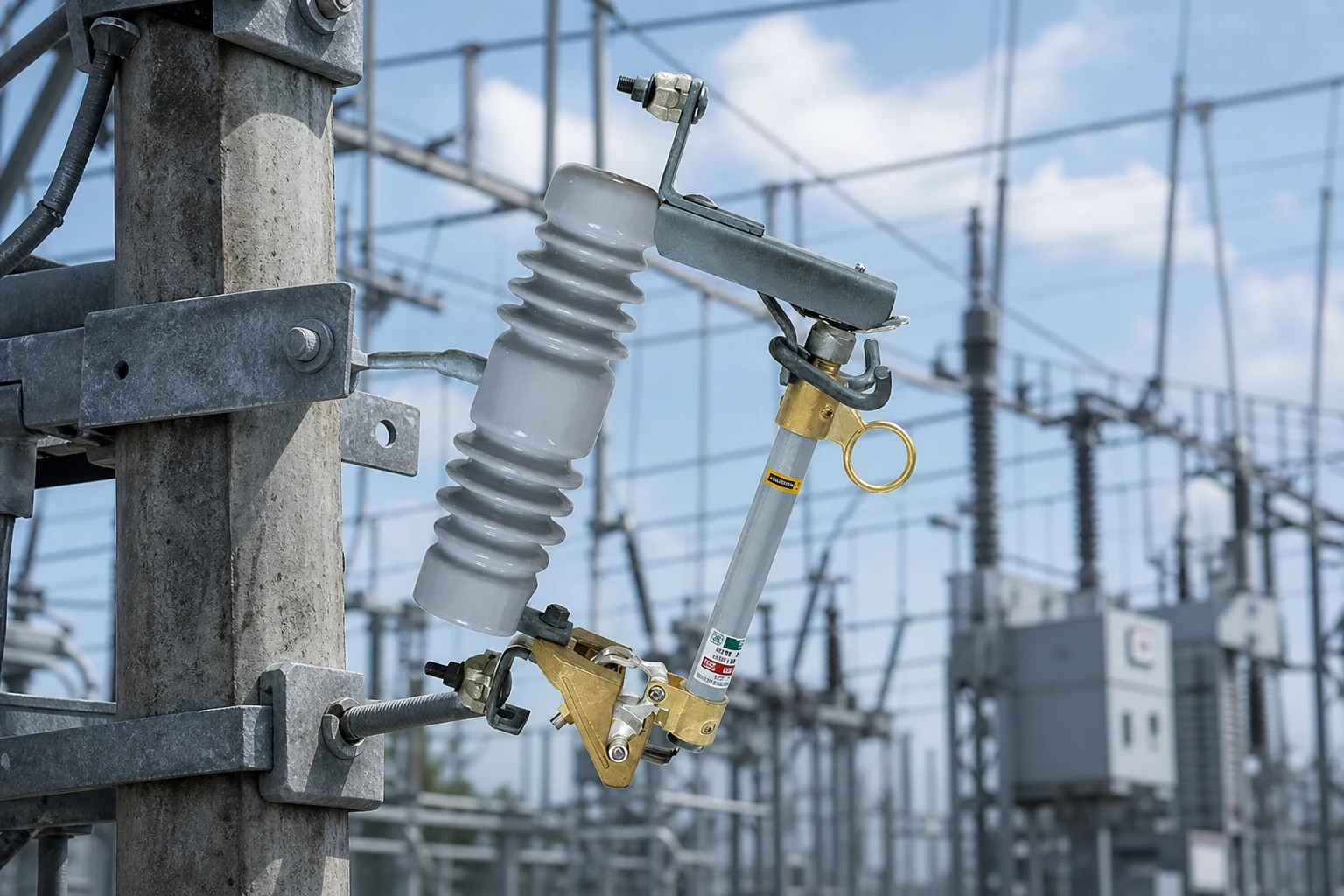
Continuous current is a thermal selection. Compare the normal load, expected cold-load pickup, transformer inrush and any planned load growth with the link’s curve and the body’s terminal limits. Avoid repeating a blanket “100–300 A” range: the acceptable current is configuration- and study-dependent, and the link may be the limiting element.
Interrupting rating is a fault-clearing requirement, not a marketing maximum. Obtain the prospective short-circuit current at the installation point, including source changes or distributed generation where applicable. Then verify the tested combination of cutout body and link at that duty, with the required power-frequency and impulse withstand evidence. A body that carries the load can still be unsuitable if the link or assembly cannot interrupt the calculated fault.
For a practical RFQ, attach the single-line diagram, fault-current calculation, transformer data, conductor size, altitude and pollution description. That package gives the supplier a reproducible basis for selecting a link and prevents a quotation from silently substituting a different carrier or terminal arrangement.
Check fuse-link TCC and loadbreak limits
Plot the selected fuse link’s time-current characteristic (TCC) against transformer damage limits, downstream protective devices and any upstream recloser or breaker curves. The goal is selective operation: a downstream problem should clear at the nearest practical device, while normal energization and cold-load pickup should not melt the link. K- and T-speed names are not interchangeable across manufacturers; compare the actual published curves and tolerances.
A drop-out cutout provides visible open indication after the link operates, but that does not automatically make it a load-break switch. Confirm the manufacturer’s stated switching duty, the approved hook-stick procedure and whether the installation requires a separate disconnector switch. Never infer loadbreak capability from the presence of a hinged carrier.
Document the boundary in the single-line diagram and operating instructions: which device clears a fault, which device provides isolation, and which operations require de-energization. This distinction helps line crews avoid using a dropout motion as a substitute for an approved load-interruption procedure.
Verify site clearances and utility acceptance
Outdoor cutouts see rain, dust, salt, ultraviolet exposure, wind and temperature cycling. Describe the site’s pollution severity, altitude, washdown practice and mechanical exposure so the supplier can state the relevant creepage, clearance and material assumptions. A polymer or porcelain housing is not, by itself, proof of suitability for a coastal or high-altitude site; the complete insulation design and the utility’s acceptance criteria control.
Ask for drawings that show open-position clearance, phase spacing, mounting angle, live-part envelope and connection hardware. Check those dimensions against the pole, crossarm and conductor sag calculation. Where a utility has an approved-equipment list, submit the exact body/link combination and revision-controlled drawings rather than a generic catalogue family.
IEC 60282-2:2008 is the relevant IEC scope for expulsion fuses and their associated tests; it is not a blanket certification of every field installation. IEC 62271-111:2019 covers automatic circuit reclosers, so cite it only when a recloser is part of the coordination scheme. The contract should identify the governing standard edition, required test evidence and the authority that accepts the equipment.
If the site needs a different insulator or creepage arrangement, keep that change tied to the approved drawing. A separate insulator selection may be relevant to the broader pole design, but it does not replace the cutout manufacturer’s insulation evidence.
Compare hardware, spares and acceptance evidence
Normalize quotations by the same body, link family, terminal arrangement, mounting hardware, documentation and spare-link quantity. Ask the supplier to identify exclusions: field assembly, special brackets, utility witness testing, replacement carriers and freight packaging. Do not rank offers on unit price when one quote omits the evidence or hardware needed for acceptance.
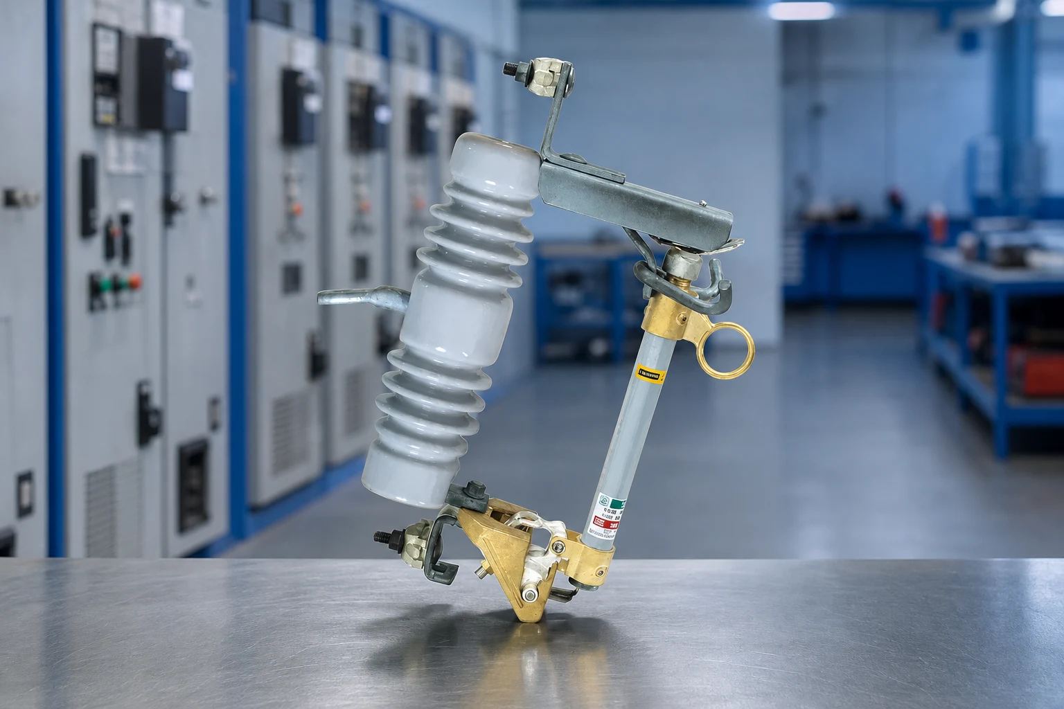
| Observed or foreseeable failure | Likely selection or process gap | Preventive check |
|---|---|---|
| Link operates during energization | TCC not checked against transformer inrush or cold-load pickup | Review the actual curve with transformer data before release |
| Fault is not cleared as expected | Available fault current or tested link/body combination was omitted | Attach the fault study and request matching interruption evidence |
| Flashover or tracking appears at site | Pollution, altitude or clearances were assumed rather than specified | Approve the site arrangement drawing and insulation assumptions |
| Crew cannot perform planned switching | Dropout was treated as loadbreak equipment without a stated duty | Record the operating boundary and provide an approved device if needed |
| Utility rejects the shipment | Wrong standard edition, missing report or unapproved configuration | Obtain written acceptance of the exact bill of materials and reports |
Before shipment, freeze the bill of materials and serial-number format, review the nameplate artwork, and request the installation drawing, link curves, test report excerpts and spare-parts list. At handover, retain the approved drawing and the as-installed link type with the commissioning record. Buyers can review the fuse cutout range as a starting point, then request a project-specific configuration review rather than assuming the catalogue default is correct.
Five checks before specifying a fuse cutout
- Record maximum system voltage, frequency, grounding, normal load, transformer inrush and prospective fault current at the pole.
- Choose the cutout body and compatible link family as one tested assembly; confirm terminals, carrier, mounting and operating orientation.
- Overlay the link TCC with transformer damage, downstream protection and upstream recloser or breaker curves.
- Check open-position clearance, pollution and altitude assumptions against the approved pole arrangement.
- Put the standard edition, test evidence, utility approval path, spares and switching boundary into the purchase order.
FUERTE can review a project RFQ or drawing when the design team provides these inputs. Keep the conversation technical: the useful output is a traceable body/link selection with clear limits, not a universal rating promise.
Fuse cutout ratings and operating limits: FAQs
Is the cutout body rating the same as the fuse-link rating?
No. The body covers the carrier, terminals, insulators, hardware and clearances; the link contributes the melting and interruption behavior. Specify and verify the complete compatible assembly.
Which fault current determines interrupting duty?
Start with the prospective fault current at the installation point, including relevant source or generation changes. Then confirm that the selected body and link combination has test evidence for that duty under the governing utility standard.
Does visible dropout permit loadbreak switching?
Not automatically. A dropout provides visible open indication after operation, but load-interruption duty must be expressly stated and supported by the manufacturer and utility procedure. Use a separate approved switching device when that duty is not documented.
Which TCC determines link speed for a transformer tap?
Choose from the published TCC after checking transformer inrush, cold-load pickup, normal load and downstream protection. K- or T-speed labels alone are not enough because naming and tolerances vary by manufacturer.
Which site conditions belong in the RFQ?
State altitude, pollution or salt exposure, rainfall or washdown conditions, temperature range, wind or mechanical constraints and the required phase and ground clearances. The supplier should show how those assumptions appear on the approved arrangement drawing.
Which documents establish utility acceptance?
Request the exact bill of materials, nameplate, outline and installation drawings, link TCC, applicable type-test evidence, standard edition and operating instructions. Match the documents to the configuration that will actually be installed, including the spare-link type.
Specify the assembly and operating limit before ordering
A dependable overhead fuse cutout decision is a documented coordination exercise. Start with the system study, then match the cutout body, fuse link, interruption duty, insulation clearances and operating method as one assembly. Plot the actual TCC against transformer and feeder limits, state the dropout/loadbreak boundary, and give the utility the exact drawings and test evidence it must approve. Environmental details such as pollution and altitude belong in the same review because they change the insulation assumptions. When quotations are normalized for hardware, spares and documentation, the lowest apparent price no longer hides an acceptance gap. The memorable rule is simple: specify the fault, prove the assembly, and define the operation before ordering. For a project review, send the approved parameters to FUERTE engineering support.
Referencias
- IEC 60282-2:2008 — High-voltage fuses, Part 2: Expulsion fuses (official IEC publication)
- IEC 62271-111:2019 — High-voltage switchgear and controlgear, automatic circuit reclosers (official IEC publication)
- IEEE C37.42-2016 — Specifications for distribution cutouts and fuse links
- IEEE C37.41-2024 — Design tests for high-voltage fuses and accessories