








When a maintenance team replaces a failed protective device, the fastest option is often to match the ampere marking and move on. That shortcut can create a serious mismatch: a fuse link selected for current alone may not safely interrupt the available fault current, while an HRC fuse may be specified for a duty the installation does not require. The visible failure is a blown element; the underlying issue is usually selection, system fault level, coordination or installation practice. This guide compares HRC fuses and fuse links, explains what “breaking capacity” actually means, and gives a practical path for choosing, inspecting and ordering the correct device.
Summary: An HRC fuse is a fuse assembly designed and tested to interrupt a stated high prospective fault current under its applicable standard; “fuse link” usually describes the replaceable fusible element and may refer to several voltage and construction classes. IEC 60269 governs low-voltage fuse systems, while IEC 60282-2 covers high-voltage current-limiting fuses. A 100 A current rating alone does not determine breaking capacity. Confirm the system voltage, prospective short-circuit current, utilization category, time-current coordination and the manufacturer’s tested data before purchase.
What is the practical difference between an HRC fuse and a fuse link?
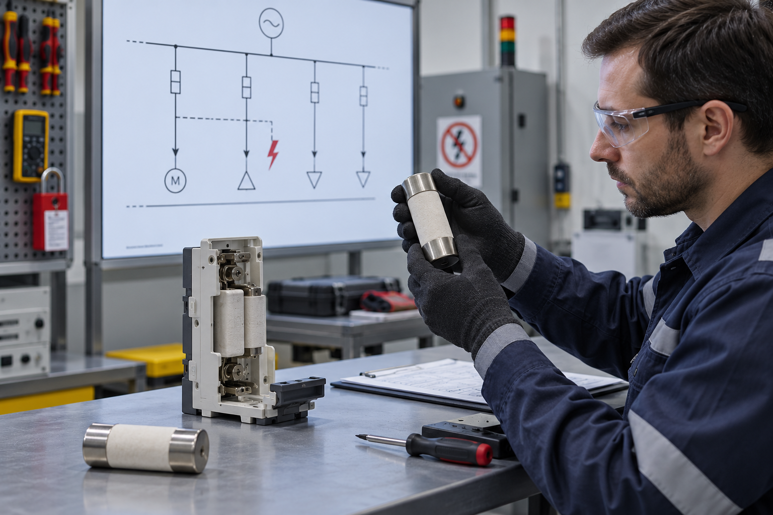
HRC means high rupturing capacity. In a low-voltage cartridge or bolted fuse system, the complete fuse typically combines a calibrated fusible element, an arc-quenching filler, end contacts and a body that contains the fault. The assembly is tested for interrupting duty, temperature behavior and other characteristics within the relevant IEC 60269 system. The term describes a capability and construction, not a universal shape or one fixed current range.
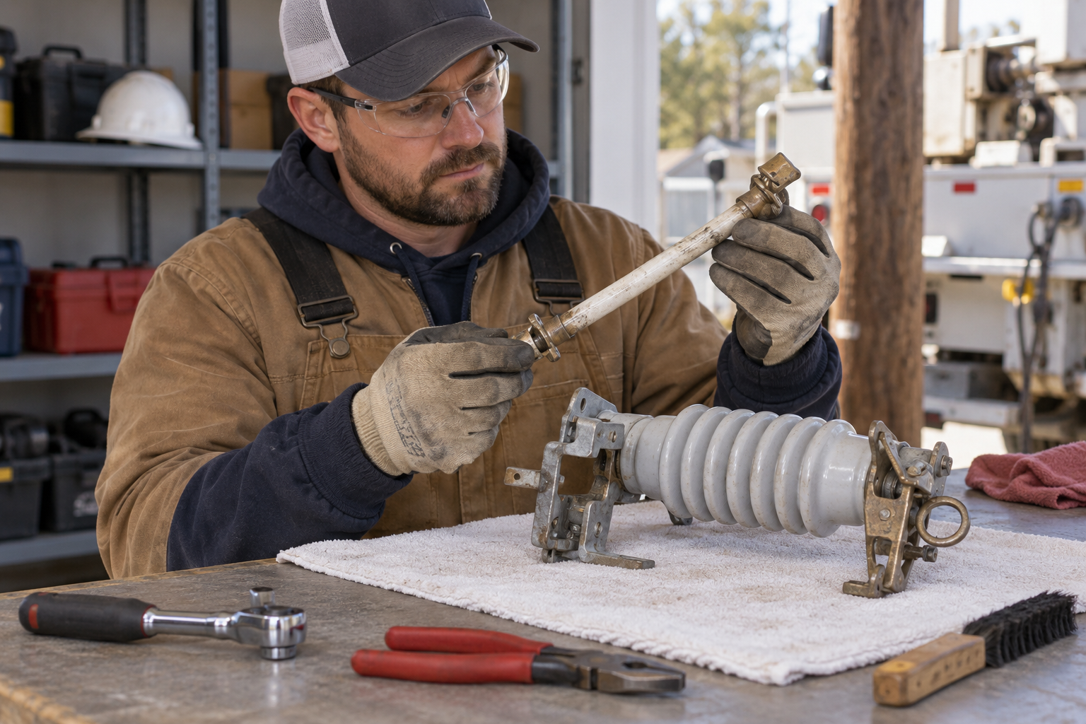
A fuse link is the replaceable part that melts when its current-time characteristic is exceeded. In a cut-out, for example, the link may be a removable expulsion or drop-out link; in a cartridge system it may be the internal element or a replaceable cartridge link. “Fuse link” therefore needs a voltage class, standard, body style and characteristic before it can be compared fairly with an HRC fuse.
How does HRC fuse breaking capacity relate to available fault current?
Breaking capacity is the highest prospective fault current that a fuse can interrupt safely at a stated voltage and power-factor or test condition. The installation’s available fault current must be established at the fuse location, then compared with the device’s tested breaking-capacity declaration. IEC 60269-1 defines common low-voltage fuse-system requirements and verification tests; product parts add the system-specific details.
If the available fault current exceeds the fuse’s declared capacity, the fuse may fail to clear the circuit safely. If it is far below the declared capacity, that does not automatically make the fuse unsuitable; coordination, let-through energy, voltage drop and operating class still matter. For high-voltage current-limiting applications, IEC 60282-2 and the applicable utility or equipment specification set the test framework. IEEE C37.41 and IEEE C37.42 are commonly referenced for distribution-class fuse and fuse-link performance in North American practice.
How do time-current curves guide fuse-link selection?
A time-current curve shows how quickly a link is expected to operate at different multiples of rated current. The curve is read with the load’s normal inrush, overload profile and downstream/upstream protection curves. A link that is too fast can open during a permitted motor or transformer inrush; one that is too slow can lose selectivity or allow damaging energy to pass.
Selection should therefore compare the manufacturer’s pre-arcing and total-clearing curves at the actual prospective current. Verify the curve revision, ambient-temperature assumptions and whether the published values are minimum, maximum or mean times. IEC 60269 utilization categories such as gG, aM and related designations communicate intended duty, but the category does not replace coordination studies or equipment instructions.
Which protection option fits common applications?
| Dimension | HRC fuse assembly | Fuse link used in a cut-out or carrier |
|---|---|---|
| Primary role | Contained current interruption with a declared tested duty | Replaceable fusible element matched to a carrier and application |
| Breaking-capacity evidence | Declared for the complete fuse system at stated voltage and test conditions | Must be checked for the complete link/carrier system and applicable standard |
| Typical coordination task | Compare total-clearing curves with upstream and downstream devices | Match link curve to transformer, feeder or cut-out coordination requirements |
| Installation constraints | Correct size, contact system, enclosure and heat dissipation are required | Correct cut-out geometry, striker or indicator arrangement and mechanical fit are required |
| Replacement control | Use the same system, voltage class, current, category and manufacturer data | Use the specified link type; do not substitute by ampere marking alone |
What procurement and inspection checks prevent the wrong replacement?
Procurement records should capture the conditions that define the device’s duty, not just a nominal current. The following checklist can be attached to a request for quotation or maintenance work order.
| Check | Evidence to request or record | Why it matters |
|---|---|---|
| System identity | Voltage, frequency, phase arrangement and equipment location | Prevents mixing low-voltage and high-voltage fuse systems |
| Fault duty | Prospective short-circuit current calculation or utility study at the installation point | Confirms the required breaking-capacity margin |
| Characteristic | Utilization category and time-current curves from the manufacturer | Supports selectivity and inrush tolerance |
| Physical fit | Dimensions, contacts, mounting, striker/indicator and carrier details | A correct rating is unsafe if the assembly cannot dissipate heat or make reliable contact |
| Condition on removal | Cracks, discoloration, loose contacts, corrosion, moisture or evidence of arcing | Separates an overload event from installation or environmental damage |
What inspection signs show that an HRC fuse or fuse link needs replacement?
A visible open indicator or a continuity test performed with the circuit isolated can confirm that a link has operated, but neither test proves that the rest of the assembly is healthy. Inspect for heat discoloration at contacts, pitting, cracked ceramic or polymer parts, damaged threads, contamination, moisture ingress and a carrier that no longer latches or seats correctly. Follow the equipment maker’s isolation, proving-dead and discharge procedure; do not rely on a visual check inside an energized enclosure.
Repeated operation deserves a cause investigation. Compare the event current and time with the curve, check terminal torque and cable condition, and review motor or transformer inrush. Replacing a link with a higher ampere rating without a coordination review can move the fault to a less protected part of the system.
What standards apply to HRC fuses and fuse links?
IEC 60269 is the principal low-voltage fuse standard family. It defines general requirements and product-system parts, including test methods and performance declarations. IEC 60282-2 addresses high-voltage current-limiting fuses, with application-specific requirements that differ from low-voltage cartridge practice. In IEEE-based distribution systems, C37.41 and C37.42 provide commonly used performance and application references for distribution-class fuses and fuse links.
These standards are not a blanket certification claim for every product. The buyer must verify the exact edition, product part, voltage class, utilization category, test report or declaration, and the destination market’s rules. A supplier that cannot identify the applicable standard and tested rating leaves the purchaser carrying the compliance and outage risk.
How should a buyer select and specify the replacement?
- Record the system voltage, frequency, installation category and available fault current at the device location.
- Define the required current rating from the protected conductor and load, then check inrush and continuous-load assumptions.
- Compare time-current curves and let-through information with upstream and downstream protective devices.
- Confirm the complete mechanical interface, dimensions, contact pressure, indicator/striker option and enclosure heat conditions.
- Request the current data sheet, applicable standard reference and traceable batch or inspection information before release.
Fuerte can be considered when a project needs documented fuse links and medium-voltage cut-out components matched to a defined application. Buyers can review the site’s dropout versus loadbreak fuse-cutout comparison, use the fuse-cutout parts identification guide during inspection, and browse other products for related protection hardware. Final selection should remain tied to the project’s verified electrical and mechanical data.
Frequently asked questions about HRC fuses and fuse links
What is the difference between a normal fuse and an HRC fuse?
“Normal fuse” is an informal label and may describe a basic fuse with limited documented interrupting duty. An HRC fuse has a declared high rupturing capacity demonstrated by tests for its specified voltage, construction and application class. Compare the complete product data rather than relying on the label alone.
What is the difference between a fusible link and a fuse?
A fusible link is the meltable element or replaceable link; a fuse is the protective assembly that includes the link and the parts that contain and extinguish the arc. In some catalogs, “fuse link” is also used as shorthand for a complete replaceable cartridge, so the manufacturer’s terminology and drawing must be checked.
What is the difference between a fuse link and a fuse cutout?
The fuse link is the replaceable current-sensing element. A fuse cutout is the outdoor support, holder and switching or dropout assembly that accepts a specified link and provides insulation and visible operation. They must be compatible in voltage class, dimensions, contacts and interrupting duty.
What is the typical breaking-capacity range of an HRC fuse?
There is no single universal range. Breaking capacity depends on the fuse system, voltage, utilization category, construction and the test standard; product data sheets may state values from kiloampere levels to much higher duties. Use the tested value for the exact catalog number and system voltage.
What is the breaking capacity of a 100 A HRC fuse?
The 100 A marking identifies the rated current, not the interrupting capacity. A 100 A HRC fuse can have different breaking-capacity declarations at different voltages and in different product systems. The answer must come from the exact manufacturer data sheet or test documentation.
What are the common causes of HRC fuse failure?
Common causes include overload, short circuit, excessive inrush, poor contact pressure, loose or overheated terminals, contamination, moisture, incorrect replacement and an available fault current beyond the fuse’s tested duty. Investigate the circuit and assembly before installing a new fuse.
Conclusion: how should the final choice be made?
HRC fuse versus fuse link is a question about the complete protection system, not a contest between two ampere markings. First establish the voltage class and available fault current; then select the current rating and utilization category that fit the load and conductors. Use time-current curves to verify inrush tolerance and coordination, and confirm that the carrier, contacts, enclosure and indicators match the specified device. A 100 A rating cannot be used as a shortcut to breaking capacity, and a visual replacement cannot replace an isolation and cause investigation after a fault. IEC 60269, IEC 60282-2 and applicable IEEE references provide the framework, while the exact product documentation supplies the binding values. Fuerte’s fuse-link and cut-out resources can support the identification and sourcing stage when the project data is complete; contact the supplier with the verified electrical and mechanical schedule for a product-specific review.
References
- IEC 60269 series, Low-voltage fuses, International Electrotechnical Commission: iec.ch.
- IEC 60282-2, High-voltage fuses — Part 2: Current-limiting fuses, International Electrotechnical Commission: iec.ch.
- IEEE Std C37.41, IEEE Standard Design Tests for High-Voltage (>1000 V) Fuses and Accessories, IEEE: standards.ieee.org.
- IEEE Std C37.42, IEEE Standard Specifications for High-Voltage (>1000 V) Expulsion and Current-Limiting Fuses and Accessories, IEEE: standards.ieee.org.