
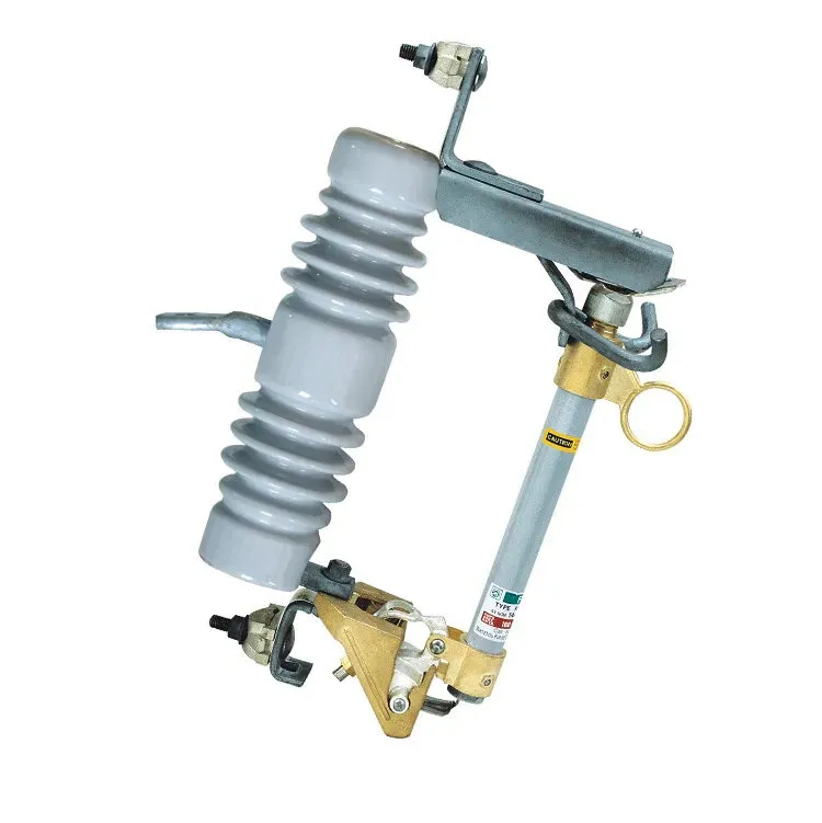
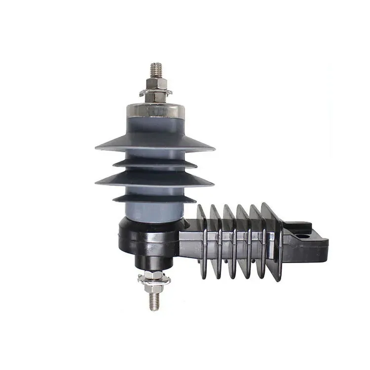
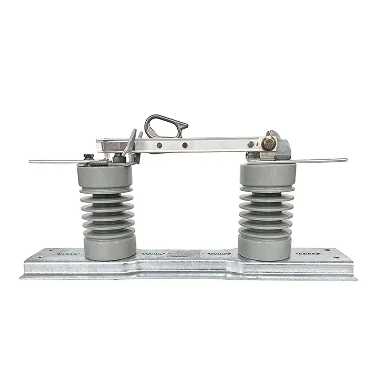
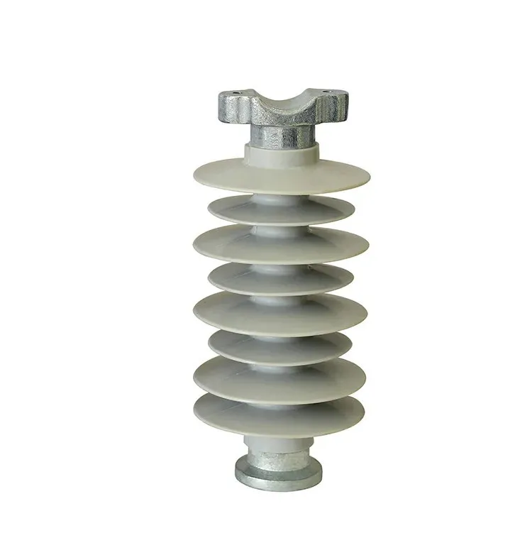
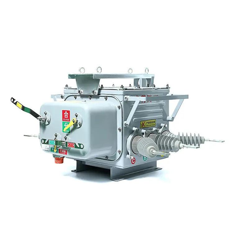
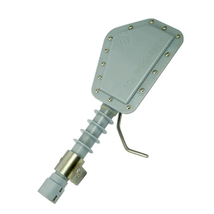


An outdoor отделяющий переключатель can satisfy an electrical schedule and still be difficult to install or operate on the intended pole. Mounting centres, conductor approach, operating-rod alignment and the space needed for blade travel are separate design questions. A photograph of a similar overhead installation cannot settle them. The specification should join the network duty to a dimensioned structure drawing and an agreed operating method. This guide focuses on the overhead-line interfaces that need to be resolved before manufacture, including support loads, environmental exposure and access for inspection.
Specify an overhead-line isolating switch from the required isolation duty, electrical ratings, support arrangement and operating sequence together. IEC 62271-102 addresses AC disconnectors and earthing switches; it does not supply the project’s pole geometry or authorize load interruption. Provide the structure drawing, terminal and conductor information, mounting orientation, full operating envelope and site conditions. Ask the supplier to return a dimensioned arrangement and mechanism details. The structure designer and line owner must confirm support, clearances and access for the complete installation.
Which pole and crossarm dimensions must be shown?
Identify the support type, mounting faces, hole centres and available working space on a dimensioned drawing. Record whether brackets are existing, supplied with the switch or designed by others. Include the space swept by moving blades and linkages, not only the closed-device outline.
The support design must account for the actual equipment and project loads. Conductor forces, mechanism reaction and environmental loading belong with the responsible designer. The supplier should provide the required equipment interface information rather than ask the installer to infer it from a family photograph.
How do conductor approaches affect the terminal arrangement?
Show the approach direction and the proposed clamp or terminal interface for each conductor. Confirm conductor material and size, fitting scope and any movement allowance required by the approved design. A matching terminal-hole count alone does not settle the connection design.
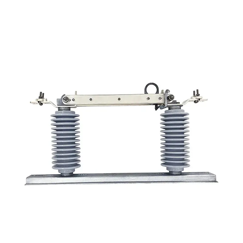
Clearances must be reviewed over the full operating movement and against adjacent phases and grounded structures. Use the line owner’s insulation and clearance requirements; do not copy a distance from a different voltage class or installation photograph.
Use a disconnector RFQ checklist to keep the support, conductor and mechanism documents together when asking suppliers to quote.
| Drawing or record | Information to include | Responsible review |
|---|---|---|
| Structure drawing | Mounting faces, holes and support arrangement | Structure designer |
| Conductor interface | Approach, fittings and terminal details | Line designer and supplier |
| Mechanism drawing | Rod route, supports and full travel | Supplier and owner |
| Site schedule | Environmental basis and access constraints | Owner or EPC engineer |
What needs checking along the operating-rod route?
Trace the complete route from the operator position to the switch mechanism. Identify rod supports, joints, adjustment provisions, handle location and lockable positions. A mechanism drawing should show how final travel is obtained without relying on field bending or unapproved alterations.
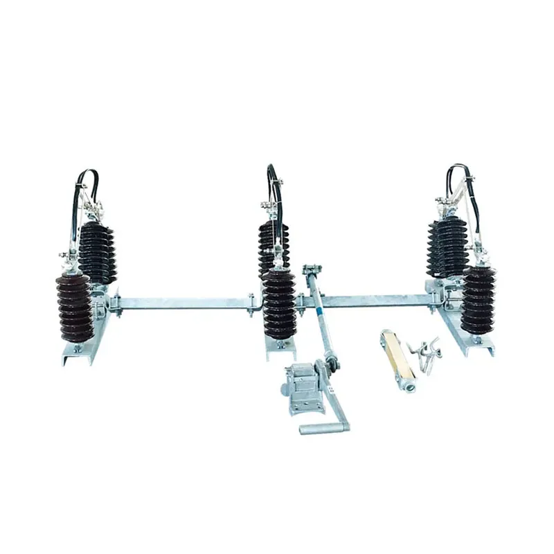
Commissioning checks should establish full opening and closing, phase coordination where relevant, position indication and the intended securing arrangement. The limits and procedure must come from the manufacturer and owner. These functional checks do not establish a new switching rating.
Which site conditions and access needs belong in the enquiry?
State altitude, temperature range, pollution exposure and relevant wind, ice or other environmental conditions from the project basis. The offered insulation and mechanical arrangement must be reviewed for those conditions. Do not turn a housing material description into an unsupported service-life or pollution-performance claim.
Plan inspection access before fixing the arrangement. The owner should be able to identify the device, inspect accessible connections and mechanism condition, and carry out authorized maintenance without an improvised access method. Include the approved drawing and adjustment records in the handover package.
ЧаВо
Can an overhead isolator be ordered from voltage and current alone?
No. Those values do not define the support, conductor interfaces, operating envelope or mechanism route. Include a structure drawing and the required operating duty.
Can installers modify an operating rod to achieve full travel?
Any change needs the manufacturer’s and owner’s approved procedure. Improvised adjustment can affect alignment, final positions and mechanical operation.
Does outdoor construction establish load-breaking capability?
No. Outdoor service describes environmental application. Check any switching duty separately against the exact offered device.
What should be recorded at commissioning?
Retain the approved arrangement, equipment identity, completed functional checks, adjustments and any resolved deviations. Apply manufacturer-specific acceptance limits and owner procedures.
Резюме
Treat the pole-mounted switch, support, conductors and operating mechanism as one installation review. Electrical ratings remain essential, but the dimensioned mounting arrangement and full operating envelope determine whether the equipment can be installed and operated as intended. Resolve conductor approaches, linkage alignment, securing positions and maintenance access before release. Keep environmental assumptions with the approved drawing so they remain available when the installation is inspected or replaced. The supplier can define the offered device and interfaces; the owner and responsible designers must accept their fit within the complete overhead line.