
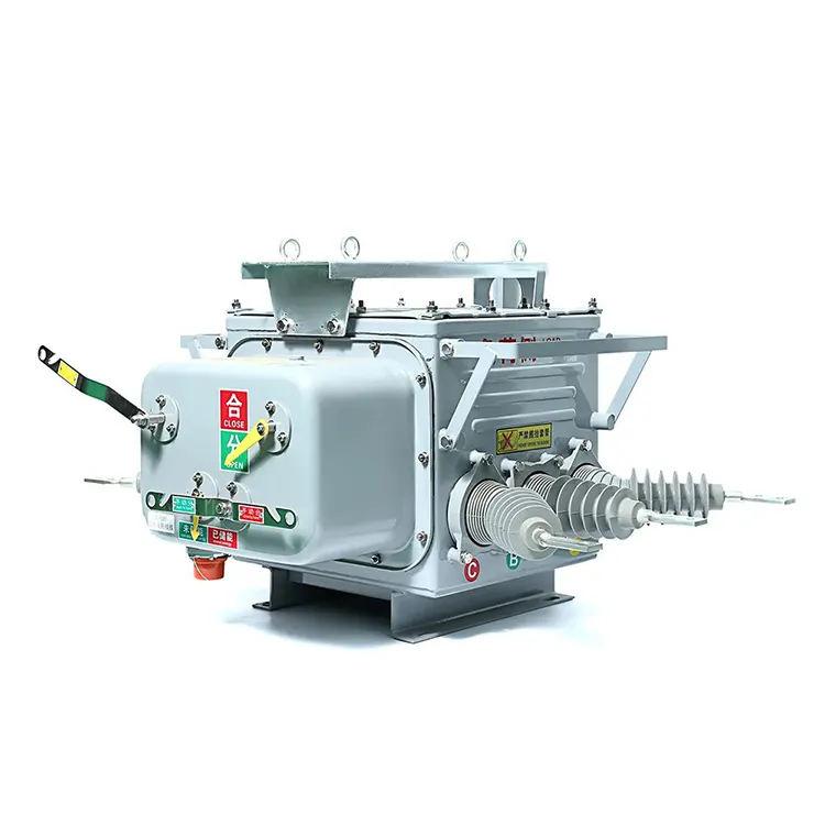
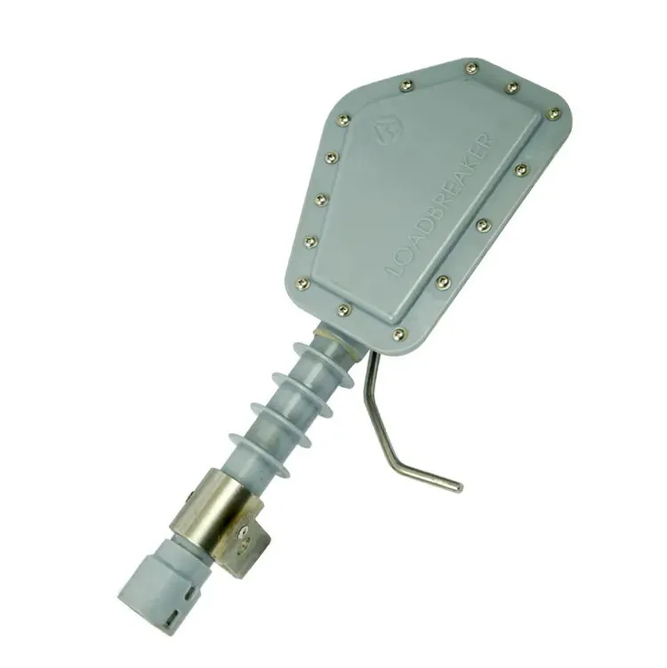


A breaker handle, a protection setting and a symbol on a drawing describe different parts of the same system. Confusing them can lead to the wrong replacement or an unsafe assumption after a trip. The current rating does not state the maximum fault current the device can interrupt, and an open indication does not by itself establish a verified isolation condition. The operating principle also varies: a small thermal-magnetic breaker can contain its own overcurrent releases, while a medium-voltage installation may use a separate protective relay and trip supply. This guide follows the process from detection to current interruption, then explains how to read the associated drawings and documents without assigning capabilities that the equipment has not demonstrated.
A circuit breaker opens its contacts to interrupt a circuit, either by an operating command or by automatic protective action. In a fault-clearing sequence, detection initiates a trip, the mechanism separates the contacts, and the interrupting system extinguishes the resulting arc and withstands the recovering voltage. Small low-voltage breakers and relay-controlled medium-voltage breakers implement these functions differently. IEC 62271-100, for example, addresses three-phase AC breakers above 1,000 V, rather than every device called a breaker. For a real installation, check the device type, protection arrangement, ratings and manufacturer’s operating instructions before interpreting its behavior.
What happens between detecting a fault and interrupting current?
The answer to how does a circuit breaker work begins with a separation of functions. A protective element recognizes a condition; a trip release acts on the mechanism; the mechanism opens the contacts; and the interrupting medium controls the arc so that current can cease. These functions may be packaged together or distributed across several components.
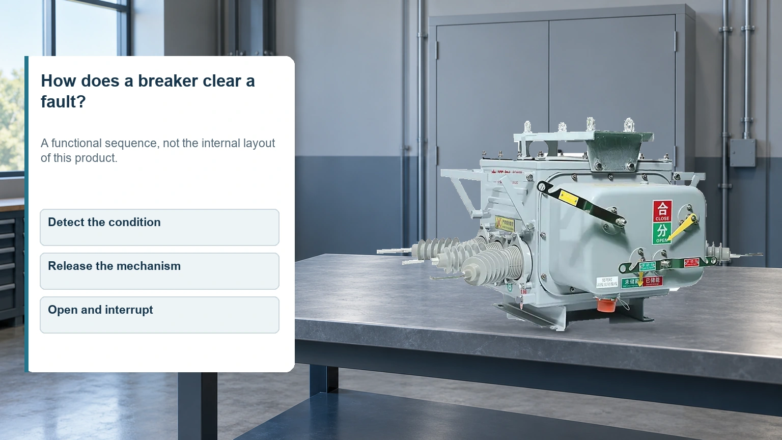
- Detect the condition: an internal release or external relay evaluates the relevant electrical quantity.
- Release the mechanism: the trip action releases the opening mechanism, subject to the actual design and control arrangement.
- Open and interrupt: moving contacts separate, an arc forms, and the interrupting system establishes the required current interruption.
A trip signal is therefore an intermediate event. Total clearing includes the relevant detection, delay, mechanism and interruption intervals. Contact movement alone is not proof that a fault has been successfully cleared. The circuit and equipment must also be within the breaker’s applicable interruption and recovery-voltage duties.
The more specific explanation of how a vacuum interrupter extinguishes an arc covers one interrupting technology. Vacuum, air and other breaker technologies should not be pictured as sharing an identical internal structure.
Why do overloads and short circuits trigger different responses?
An overload is excessive current in the intended load path. Its effect often depends on duration, so protection may allow a controlled delay. A short circuit introduces an unintended path and can require rapid operation at high current. The settings and time-current characteristics determine the actual response; neither the word “overload” nor “instantaneous” specifies one universal clearing time.
| Arrangement | How it recognizes a condition | What must be checked |
|---|---|---|
| Thermal-magnetic low-voltage breaker | Thermal overload release and magnetic high-current release | Rated current, trip characteristic and installation conditions |
| Electronic low-voltage trip unit | Electronic measurement and configured protective functions | Available functions, pickups, delays and coordination |
| External relay with a medium-voltage breaker | Relay evaluates inputs and commands a trip circuit | Instrument transformers, relay settings, trip supply and breaker duty |
The table compares architectures, not the performance of particular products. Schneider Electric’s description of low-voltage circuit-breakers explains the mechanical and protective components, while its characteristics guide distinguishes overload and short-circuit settings. Project-specific curves and coordination studies remain necessary.
A dedicated arc-fault function is another separate issue. An ordinary overcurrent release is not guaranteed to recognize a low-current series arc. Likewise, a breaker with an external trip input does not automatically include every detection function that could be connected to it.
Why can a relay-controlled breaker fail to open after a trip command?
In a relay-controlled system, successful detection depends on the rest of the operating chain. The trip supply, circuit continuity, release and mechanism must perform their assigned functions. An event record showing that the relay issued a command is useful evidence, but it does not prove that the contacts moved or the current was interrupted.
Commissioning and maintenance plans should identify which observations establish each result. Relay output, trip-circuit condition, position indication and current interruption are related but distinct pieces of evidence. The article on breaker trip circuits, controls and interlocks explains that distinction in the medium-voltage context.
This is also why a drawing showing only the main circuit is insufficient for troubleshooting a control failure. The control diagram, terminal information and manufacturer’s instructions are needed to understand the actual arrangement. A generic diagram from a different breaker is not a substitute.
What does a circuit breaker symbol tell the reader?
A circuit breaker symbol identifies a switching function within a drawing convention. Its associated device tag connects it to other project records. The same function can be represented differently in a single-line drawing, a detailed circuit diagram or another drafting system, so start with the drawing legend and cited standard.

El IEC 60617 database is the official source for IEC graphical symbols for electrotechnical diagrams. Use the symbol defined by the project’s drawing convention and confirm any additional marks against the legend. A remembered sketch is insufficient when the distinction between a breaker, switch and isolating function affects the design.
| Project document | What it helps establish | What it does not establish alone |
|---|---|---|
| Single-line diagram and legend | System arrangement and meaning of the drawn function | Every control connection or installed rating |
| Equipment schedule and data sheet | Required and supplied equipment characteristics | Actual configured protection settings |
| Control diagram | Trip, close, indication and interlock relationships | Mechanical condition or successful interruption |
| Approved protection setting record | Configured pickups, delays and enabled functions | The complete equipment interrupting capability |
If these records disagree, resolve the equipment identity and revision history before selecting a replacement. A matching symbol is not evidence that two breakers share voltage class, breaking capacity, control supply or mounting arrangement.
Which ratings matter before selecting or resetting a breaker?
Continuous-current rating, voltage rating and fault-interrupting capability answer separate questions. Trip settings determine when configured protection operates; they do not increase the device’s tested breaking capacity. Installation temperature and the specified service conditions also affect the suitability of a current rating. Schneider Electric’s fundamental characteristics guide makes these distinctions for low-voltage equipment.
For higher-voltage AC equipment, IEC 62271-100:2021+AMD1:2024 specifies its scope as three-phase breakers above 1,000 V at 50 Hz and/or 60 Hz. Citing that scope is not a claim that an individual product has passed every test. A project review should request the relevant ratings, documentation and test evidence for the selected configuration. The guide to matching breaker ratings to protection requirements develops those checks.
A breaker that has tripped should not simply be reset until it stays closed. Within its applicable U.S. workplace scope, OSHA 1910.334(b)(2) prohibits repetitive manual reclosing and requires a safe-to-energize determination. Preserve the indication and investigate the cause under the approved procedure. Switching off a breaker also does not, by itself, complete isolation, lockout and verification of the absence of voltage.
What else do readers ask about circuit breakers?
How does a circuit breaker work?
A breaker separates contacts and controls the resulting arc to interrupt current. Automatic fault clearing also requires an appropriate detecting and tripping arrangement, either built in or connected externally.
What is the difference between overload and short-circuit tripping?
Overload protection addresses excessive current in the intended path, generally with a time-dependent response. Short-circuit protection addresses fault conditions through its configured high-current or other protective functions.
What does a circuit breaker symbol show?
It represents the device function under the drawing’s convention. Use the legend and equipment tag to locate the detailed specification; the symbol alone does not give breaking capacity or trip settings.
What happens when breaker contacts open?
An arc may carry current while the contacts separate. The interrupting system must extinguish it and establish sufficient dielectric withstand for the recovering voltage under the applicable duty.
How do trip mechanisms differ between breaker types?
Some low-voltage breakers contain thermal-magnetic or electronic releases. Many medium-voltage systems use a protective relay and a separate trip circuit. The mechanism and control-energy arrangements are design-specific.
What does a breaker current rating mean?
It describes the current-carrying duty under specified conditions. It is distinct from fault-breaking capacity and may differ from an adjustable protection setting.
Why should a tripped breaker be investigated before resetting?
The cause may remain, and the fault may have affected equipment condition. Preserve trip evidence and establish whether restoration is permitted by the applicable procedure and manufacturer guidance.
Can a circuit breaker also serve as an isolating device?
Some are specifically suitable for isolation under their applicable standard and markings. Confirm that function for the actual device and installation. An open indication alone does not establish a verified electrically safe work condition.
Referencias
- Schneider Electric: Standards and description of circuit-breakers.
- Schneider Electric: Fundamental characteristics of a circuit-breaker, updated August 2026.
- IEC 60617: Graphical symbols for diagrams, official database.
- IEC 62271-100:2021+AMD1:2024: Alternating-current circuit-breakers.
- OSHA 1910.334: Use of equipment.
Resumen
A breaker works through a chain of detection, tripping, contact movement and successful interruption. Understanding that chain is more useful than assuming that every breaker contains the same release or responds to every electrical hazard. Begin a selection or investigation with the voltage class and circuit duty, then confirm the detection functions, control arrangement and equipment ratings. Read the drawing symbol alongside the equipment schedule and control documents. After a trip, preserve the evidence and establish the conditions for restoration instead of using repeated resets as a test. Fuerte’s ZW20 outdoor vacuum circuit breaker provides a specific product reference for distribution equipment reviews; its suitability must be checked against the project’s actual protection and installation requirements.