








Selecting a lightning arrester for distribution transformer duty answers only half of the procurement question. The other half is physical: where the unit mounts on the structure, how the leads run, how the arrester sits relative to the fuse cutout and bushings, which grounding connection it uses, and what the crew records before energization.
This guide covers that installation half. System inputs and device selection are handled by two earlier articles in this cluster, and both are linked below rather than rewritten here.
Part 1. Installation questions, not selection
Three questions arrive together in most distribution transformer protection projects: what system conditions apply, which device fits those conditions, and how the chosen device gets installed and accepted. Each question has its own evidence, and mixing them produces gaps that surface late, usually during the site walk-down.
For the first question, the live article on transformer surge arrester coordination questions defines the system voltage, grounding, insulation, and study inputs a buyer must assemble. For the second, the metal-oxide surge arrester selection workflow walks through the device-selection sequence. Start with the lightning arrester portfolio if you need family-level orientation first. For a related technical topic, see Line Arresters for Overhead Distribution: Placement and Coordination Basics.
This page assumes those two stages produced an exact quoted SKU. Everything below asks how that SKU reaches the transformer structure in a documented, verifiable arrangement.
Part 2. Decide the mounting position on the structure
Mounting position is a drawing decision, not a field improvisation. Pole-top, crossarm, transformer-tank bracket, and pad or enclosure arrangements each change the bracket type, the lead path, and the working space around the transformer, so the installation drawing should state which arrangement applies and which hardware it assumes.
Ask the supplier for the mounting dimensions and bracket options of the exact quoted SKU, then compare them against the structure drawing before dispatch. A mismatch discovered at the warehouse costs a revision; the same mismatch discovered up the pole costs an outage window.
Field crews also need the position stated in relation to the equipment already on the structure. An arrester drawn in isolation tells the crew very little about which side of the transformer it occupies, how it clears the cutout swing path, or where its grounding connection lands.
Part 3. Review lead length and routing
Lead length belongs in the installation review because the installed path, not the catalog sheet, is what the protection review must consider at the transformer terminals. Long or looping leads add to what the review has to evaluate, which is why installation practice keeps connections short and direct wherever the structure allows.
Routing deserves the same attention as length. Record where each lead starts and ends, which conductors it crosses, and what it must clear during operation and maintenance. Keep the routing on the installation drawing so the reviewer and the crew are reading the same geometry.

Published guidance exists for this stage: IEC 60099-5 collects selection and application recommendations for surge arresters, and the project engineer applies it together with owner rules. This article does not restate clause content or numeric limits; it only insists that the installed lead arrangement appears in the reviewed documents rather than being left to habit.
Part 4. Coordinate cutout and bushing interfaces
A distribution transformer structure is a shared space. The arrester, the fuse cutout, the bushings, and the service conductors all claim room on it, and their relative positions are project decisions that the drawing must settle before the crew climbs.
| Interface question | What to check on the drawing | What to confirm on site |
|---|---|---|
| Arrester and fuse cutout | Which unit sits where, and how the connection order runs | Cutout operation and drop-out path stay clear of the arrester and its leads |
| Arrester and bushing | Which bushing terminal the lead serves | Lead reaches the terminal without strain or sharp bends |
| Arrester and conductors | Clearances stated for the structure | Working space and separation match the drawing |
| Arrester and grounding | Where the grounding connection lands | Connector type and path match the grounding plan |
Clearance values come from the project documents and the owner’s standards, never from a photograph or another site’s habit. When the drawing is silent on a spacing the crew needs, raise it as an engineering query instead of resolving it with field judgment alone.
Bushing interfaces deserve one extra check at delivery. Compare the connector and terminal details of the exact quoted SKU against the transformer bushing hardware, because a family-level product photo cannot confirm that the two ends actually mate.
Part 5. Verify grounding connections and installation records
The grounding connection turns the arrester from a component into part of a protection path, so its conductor, connector, and route deserve the same documentation as the line-side lead. Record what the grounding plan requires and what the crew actually installed, including any deviation the engineer approved.
Records are the deliverable of this stage. A transformer arrester installation that works but leaves no paper behind cannot be audited, maintained, or repeated on the next structure.
| Record | Content | Where it lives |
|---|---|---|
| Installation drawing | Mounting position, bracket, leads, clearances, grounding route | Project document control |
| Manufacturer instructions | Assembly steps, hardware, and torque for the exact quoted SKU | Supplier documentation set |
| As-installed notes | Deviations, substitutions, and approvals | Site quality file |
| Connection record | Line-side and grounding connections as made | Handover records |
| Photo log | Labeled images of the finished arrangement | Handover records |
Fastener torque, assembly sequence, and hardware come from the manufacturer’s instructions for the exact quoted SKU. If the instructions and the drawing disagree, the conflict goes back to the engineer in writing.
Part 6. Run the site acceptance walk-down
Site acceptance is the last point where an installation gap costs little to fix. Walk the structure against the drawing and the instruction set, item by item, before the energization request is signed.
| Walk-down item | Acceptance question |
|---|---|
| Mounting | Does the position, bracket, and orientation match the installation drawing? |
| Leads | Are length and routing as drawn, secure, and free of strain? |
| Interfaces | Do cutout, bushing, and conductor positions match the reviewed layout? |
| Grounding | Is the grounding connection complete, torqued per instructions, and on the planned route? |
| Housing | Is the unit clean, undamaged, and correctly labeled for the location? |
| Records | Are the as-installed notes, connection record, and photo log complete? |
Energization itself follows the owner’s isolation and authorization procedures. Equipment installation does not replace that process, and the OSHA electrical safety topic is a useful public reference for how controlled electrical work is framed; the governing rules remain the owner’s and the local jurisdiction’s.
Treat the signed walk-down sheet as part of the handover records. It closes the loop between the drawing, the instructions, and the structure as built.
Part 7. Plan spares and use product context
Spare parts planning is easiest at order time, while the exact quoted SKU and its accessories are already on the table. Ask the supplier to state which items are recommended as site spares for the order quantity, and record that answer with the purchase documents instead of reconstructing it years later from a nameplate.
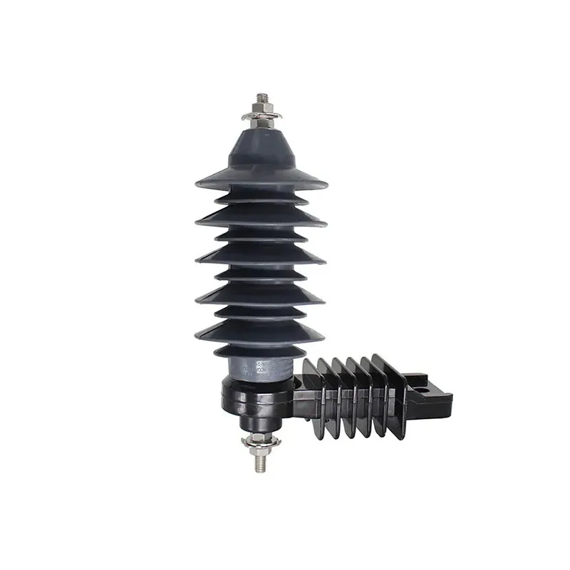
Product context helps route those requests precisely. The YH510W-21/YH510W-21J Surge Arrester page identifies one FUERTE product family whose page-level data, drawings, and documentation can be requested for a specific inquiry.

Product recommendation fit boundary
A product page proves neither mounting fit nor site suitability. Bracket compatibility, terminal hardware, clearances, and accessories are confirmed by reviewing the exact quoted SKU drawing against the project installation drawing, and every rating stays on the corresponding product page for verification. Buyers who have the structure drawing, lead routing sketch, and grounding plan ready can send the installation evidence pack and receive an SKU-level response instead of a generic one.
FAQ
Where is a lightning arrester installed on a distribution transformer?
The mounting position is set by the project installation drawing: pole-top, crossarm, tank bracket, or a pad and enclosure arrangement. Each option changes the bracket, lead path, and working space, so the drawing decides, not a default habit.
Why do installers keep arrester leads short and direct?
Because the installed lead path is part of what the protection review evaluates at the transformer terminals. Short, direct connections keep the installed arrangement close to what the review assumed, and the as-built routing is recorded on the drawing.
How should the arrester position relate to the fuse cutout?
Their relative positions are a project-drawing decision. The layout must keep the cutout’s operation and drop-out path clear of the arrester and its leads, and the connection order must match the reviewed design.
What clearances apply around a transformer arrester?
Clearances come from the project documents and the owner’s standards for that structure and voltage. This article states no numeric values; when a needed spacing is missing from the drawing, raise an engineering query.
What should a site acceptance check cover before energization?
Walk the structure against the drawing and instructions: mounting position and bracket, lead length and routing, cutout and bushing interfaces, grounding connection, housing condition, and the completeness of the as-installed records.
What installation records belong in the handover file?
Keep the installation drawing, the manufacturer instructions for the exact quoted SKU, as-installed notes with approved deviations, the connection record, the photo log, and the signed acceptance walk-down sheet together as handover records.
What spare parts should buyers include with an arrester order?
Ask the supplier to state a recommended spares list for the order quantity and site conditions, and file that answer with the purchase documents. This article does not prescribe a universal list because accessories differ by SKU.
Can a product photo confirm that mounting hardware fits?
No. A photo shows a product family’s general form. Fit is confirmed by comparing the exact quoted SKU drawing and hardware details against the transformer structure drawing before dispatch.
References
- Standard scope for application recommendations: IEC 60099-5, Surge arresters — Selection and application recommendations
- Electrical safety-process context: OSHA electrical safety topic
- Overhead distribution industry context: Utility Products overhead distribution systems section
- Public terminology context: Wikipedia: Surge arrester
What should transformer-arrester coordination records show?
A current transformer-arrester review should connect the arrester to the transformer terminal, not just to a voltage label. Record the system grounding arrangement, transformer insulation data reference, bushing and terminal geometry, lead length and routing, expected surge sources, and the study or owner criteria used for coordination. IEC 60099-5 is an application reference; the project engineer still controls the design assumptions.
The handover file should include the approved drawing, exact SKU documentation, as-installed photographs and any field deviation. Those records make it possible to investigate a later event without guessing whether the installed earth lead or mounting position matched the study.
Summary
Transformer surge protection is a coordination decision. Verify the transformer interface, grounding, lead routing and application evidence together, then preserve the approved and as-installed records.